Eureka AIR delivers breakthrough ideas for toughest innovation challenges, trusted by R&D personnel around the world.

Lead-in optical cable and manufacturing mold, manufacturing method and air tightness testing method thereof

A technology for introducing optical cables and manufacturing molds. It is applied in the directions of light guides, optics, optical components, etc., and can solve the problems of poor air tightness of optical cables, large optical fiber attenuation, and easy retraction of sleeves.

Pending Publication Date: 2021-11-30
SHENZHEN SDGI OPTICAL NETWORK TECH
View PDF0 Cites 0 Cited by
  • Summary
  • Abstract
  • Description
  • Claims
  • Application Information

AI Technical Summary

Problems solved by technology

[0003] The laying of non-self-supporting aerial optical cables requires pre-installing a steel strand capable of carrying the laid optical cable on the transmission line tower, and then hanging the optical cable on the pre-erected steel strand through secondary laying. Requires repeated construction, high labor costs and long laying time
[0004] Conventional 8-shaped self-supporting aerial optical cables can be divided into optical cables with metal reinforcement elements and non-metallic reinforcement elements. Metal reinforcement elements 8-shaped self-supporting aerial optical cables usually use steel strands or steel wires as reinforcement elements, containing metal materials, and the weight of the optical cable is large. , construction is inconvenient, easily damaged by lightning
Non-metallic reinforcing elements 8-shaped self-supporting overhead optical cables usually use glass fiber reinforced plastic rods (FRP) as reinforcing elements. Although it can solve the problems of heavy weight of optical cables and susceptibility to lightning damage, it still has loose structure, poor airtightness of optical cables, It is not easy to block water. In actual construction, the sleeve is easy to retract, which will cause large attenuation of the optical fiber

Method used

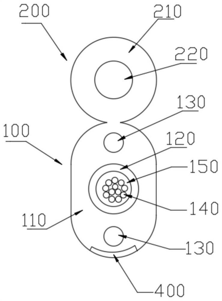
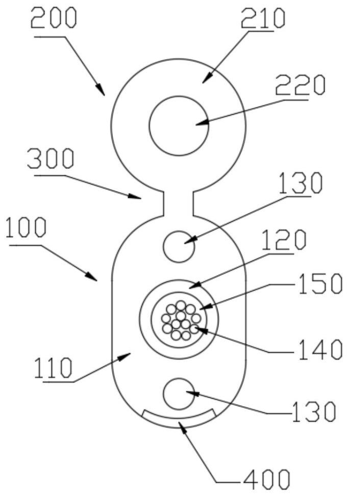
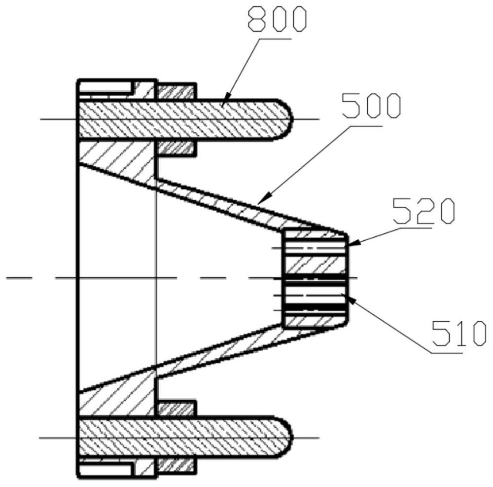

Image

  • Lead-in optical cable and manufacturing mold, manufacturing method and air tightness testing method thereof
  • Lead-in optical cable and manufacturing mold, manufacturing method and air tightness testing method thereof
  • Lead-in optical cable and manufacturing mold, manufacturing method and air tightness testing method thereof

Examples


Embodiment Construction

[0051] Embodiments of the present invention will be described in detail below in conjunction with the accompanying drawings.

[0052] It should be noted that, in the case of no conflict, the following embodiments and the features in the embodiments can be combined with each other; and, based on the embodiments in the present disclosure, those of ordinary skill in the art obtained without creative work All other embodiments belong to the protection scope of the present disclosure.

[0053] It is noted that the following describes various aspects of the embodiments that are within the scope of the appended claims. It should be apparent that the aspects described herein may be embodied in a wide variety of forms and that any specific structure and / or function described herein is illustrative only. Based on the present disclosure one skilled in the art should appreciate that an aspect described herein may be implemented independently of any other aspects and that two or more of t...


PUM

PropertyMeasurementUnit
densityaaaaaaaaaa

Abstract

The invention provides a lead-in optical cable and a manufacturing mold, a manufacturing method and an air tightness testing method thereof, which relate to the technical field of optical cable manufacturing. The lead-in optical cable comprises an optical cable part, the optical cable part comprises an optical cable outer protection layer, a sleeve and at least one first reinforcing element, and the sleeve and the first reinforcing element are located in the optical cable outer protection layer and jointly form a tight wrapping structure; at least one optical fiber is arranged in a tube cavity of the sleeve, and the tube cavity is filled with a sleeve filler in a sealing manner; the lifting part is connected with the optical cable part; and the lifting belt is connected between the optical cable part and the lifting part. According to the technical scheme, the lead-in optical cable is characterized in that when the sleeve and the reinforcing element are wrapped by the outer protective layer, a layer of glass yarn or aramid yarn is not covered outside the sleeve any more, but the sleeve and the reinforcing element are tightly wrapped inside the outer protective layer to form an integral tightly-wrapped structure, so that strain generated in construction is reduced, therefore, the lead-in optical cable does not loosen any more, and the problems that the lead-in optical cable is poor in air tightness and not easy to block water, and the sleeve is easy to retract to cause large optical fiber attenuation are solved.

Description

technical field [0001] The invention relates to the technical field of optical cable manufacturing, in particular to a lead-in optical cable and its manufacturing mold, manufacturing method and airtightness testing method. Background technique [0002] With the rapid development of my country's communication technology network, in the backbone optical fiber communication project of the power system, the original transmission line towers are used to lay optical cables in rural and mountainous areas. The two common overhead laying forms are non-self-supporting overhead optical cable laying and Conventional 8-shaped self-supporting optical cable laying. [0003] The laying of non-self-supporting aerial optical cables requires pre-installing a steel strand capable of carrying the laid optical cable on the transmission line tower, and then hanging the optical cable on the pre-erected steel strand through secondary laying. Repeated construction is required, the labor cost is high,...

Claims


Application Information

Patent Timeline
Patent Type & Authority Applications(China)
IPC IPC(8): G02B6/44
CPCG02B6/443G02B6/4432
Inventor 朱显峰陈敏柯旋李环宇黄时康
Owner SHENZHEN SDGI OPTICAL NETWORK TECH
Why Eureka
Eureka Blog
Learn More