
Pneumatic tire

A technology for pneumatic tires and treads, which is applied to special tires, tire parts, tire treads/tread patterns, etc., which can solve the problems of reduced tire electrification suppression performance and reduced discharge performance, so as to suppress separation and improve separation resistance performance effect

Active Publication Date: 2019-04-16
THE YOKOHAMA RUBBER CO LTD
View PDF8 Cites 1 Cited by
  • Summary
  • Abstract
  • Description
  • Claims
  • Application Information

AI Technical Summary

Problems solved by technology

In this way, the discharge performance from the tire to the road surface is reduced, and the electrification suppression performance of the tire is reduced.

Method used


Image

  • Pneumatic tire
  • Pneumatic tire
  • Pneumatic tire

Examples


Embodiment

[0153] Figure 9 It is a graph showing the results of the performance test of the pneumatic tire according to the embodiment of the present invention. Figure 10 It is an explanatory diagram showing a test tire of a conventional example.

[0154] In this performance test, evaluations related to (1) braking performance on ice, (2) electrification suppression performance (resistance value), and (3) separation resistance performance were performed on a plurality of different pneumatic tires (see Figure 9 ). In this performance test, a pneumatic tire having a tire size of 195 / 65R15 91Q was assembled to a rim having a rim size of 15×6J, and an air pressure of 210 [kPa] and a load specified by JATMA were applied to the pneumatic tire. In addition, the pneumatic tire was attached to a four-wheel-drive passenger car with a displacement of 3.0 [L] as a test vehicle.

[0155] (1) In the evaluation related to braking performance on ice, a test vehicle was run on a predetermined icy r...


PUM


Abstract

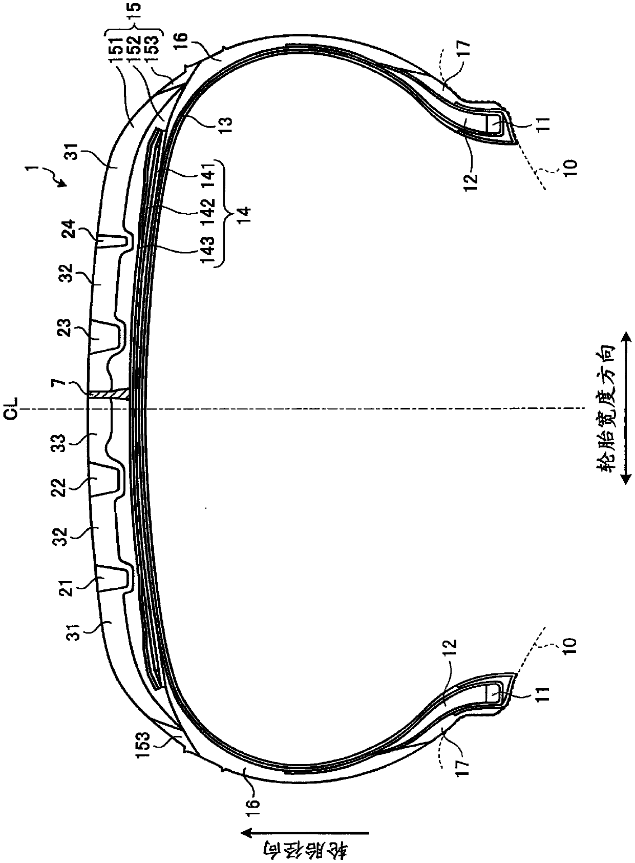
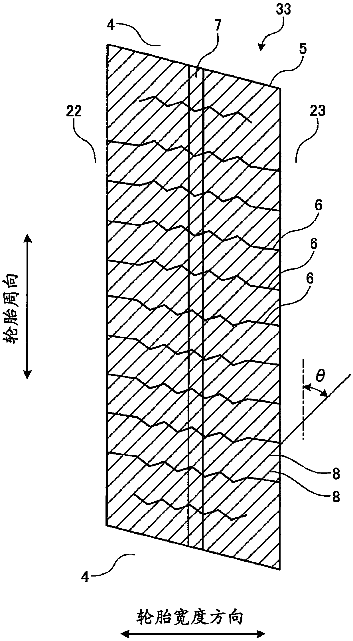
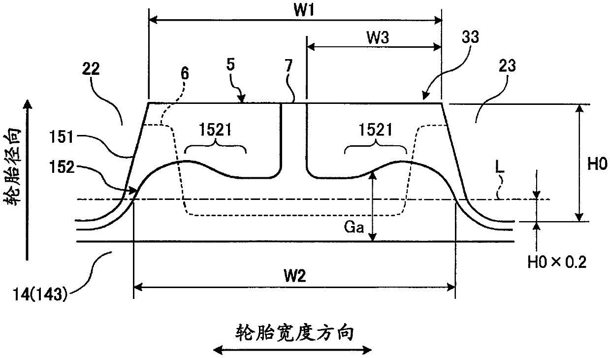
In this pneumatic tire 1, the modulus of a cap tread 151 when stretched to 300% is in the range of 3.0-7.0 (Mpa), and the modulus of an under tread 152 when stretched to 300% is in the range of 10.0-20.0 (Mpa). A grounding tread 7 comprises a rubber material having a volume resistivity of 1*10^7 (omega.cm) or less. The grounding tread 7 comprises the same rubber material as the under tread 152 andhas an integrated structure with the under tread 152.

Description

technical field [0001] The present invention relates to a pneumatic tire, and more specifically, to a pneumatic tire capable of improving the separation resistance performance of the tire while maintaining the performance on ice of the tire. Background technique [0002] In studless tires, not only the ice performance and snow performance of the tire but also the wet performance and rolling resistance are required to be improved. Therefore, in recent years, a tread structure in which the silica content in the rubber compound of the crown tread is increased has been adopted. [0003] On the other hand, silica has high insulating properties, so when the silica content of the crown tread increases, the resistance value of the crown tread increases. As a result, the discharge performance from the tire to the road surface decreases, and the electrification suppression performance of the tire decreases. Therefore, in recent studless tires, an electrification suppression structur...

Claims


Application Information

Patent Timeline
Patent Type & Authority Applications(China)
IPC IPC(8): B60C11/00B60C11/12B60C19/08
CPCB60C11/0327B60C11/1236B60C11/1259B60C11/0041B60C19/08B60C19/082B60C11/005B60C11/0306B60C2011/0025B60C1/0016Y02T10/86B60C11/00B60C11/12B60C11/11B60C2011/0353B60C2011/1213
Inventor 岸添勇
Owner THE YOKOHAMA RUBBER CO LTD
Learn More