


Quick Research
Generate reliable direction feasibility study reports for your R&D in just a few steps.

Technical Q&A
Discover and master advanced knowledge NOW. Basics, ideas, possibilities, all at once.

Find Solutions
As an expert in R&D theories, this can generate solutions to your technical problems instantly.

Evaluate Feasibility
Analyze your overall solution with one click, know your potential R&D risks in advance.

Monitor Landscape
Get weekly tech updates, stay abreast of the latest tech innovations and key insights.
Automatic control device for battery cycle test
An automatic control device and battery cycle technology, applied in program control, computer control, general control system, etc., can solve the problems of inconvenient use, bulky test equipment, etc., to avoid accidents and losses, fast installation and maintenance, charging and discharging current The effect of directional protection
- Summary
- Abstract
- Description
- Claims
- Application Information
AI Technical Summary
Problems solved by technology
Method used
Image

Examples
Embodiment 1
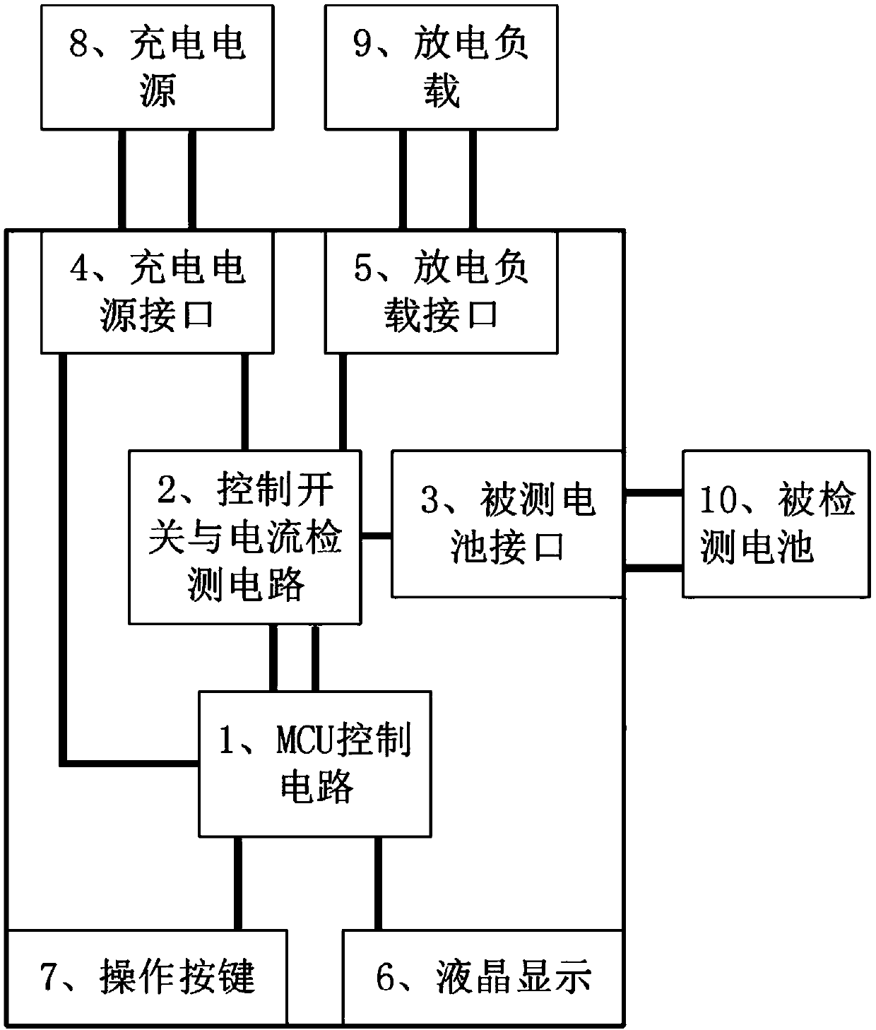
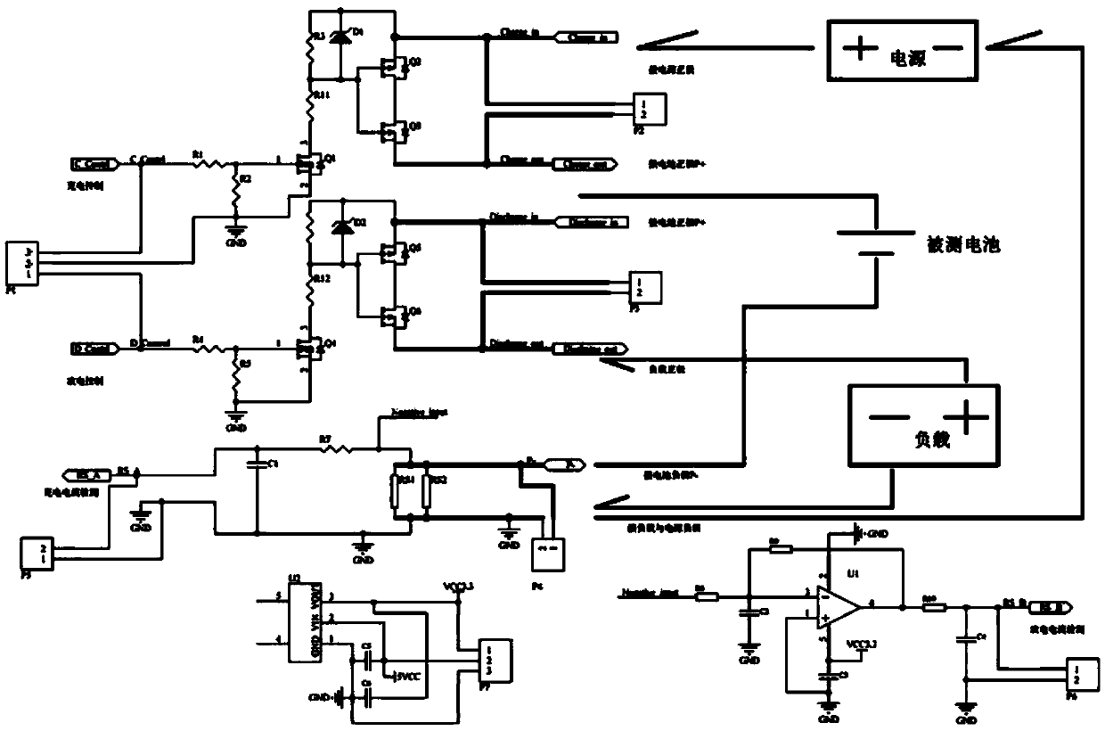
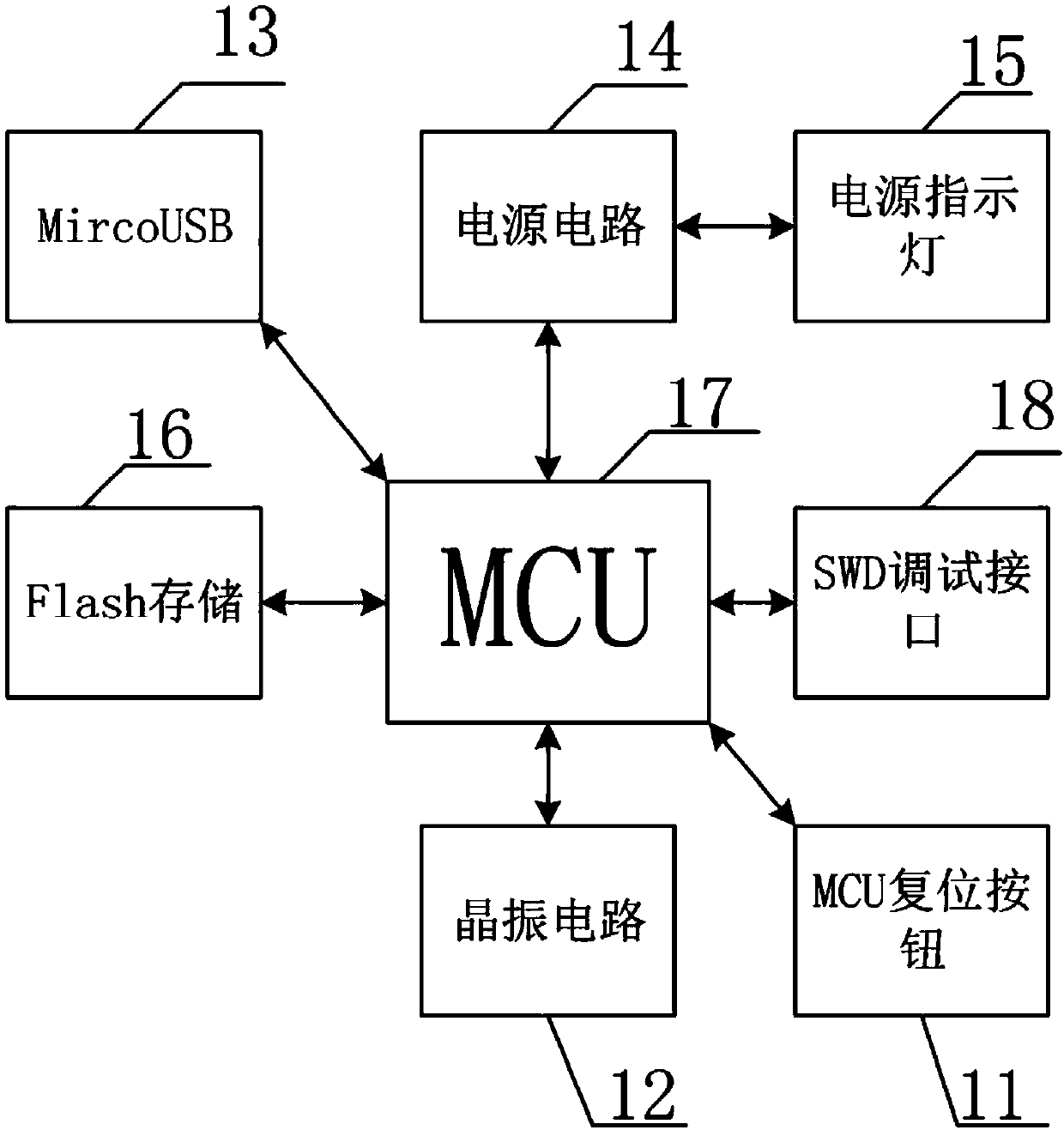
[0030] Example 1, figure 1 It is a structural schematic diagram of the present invention; figure 2 It is a schematic diagram of a control switch and a current detection circuit of the present invention; image 3 It is a schematic diagram of the MCU control circuit structure; Figure 4 It is a schematic diagram of the reverse amplifier circuit structure.
[0031] see Figure 1-Figure 4 , the present invention provides an embodiment: an automatic battery cycle test control device, including an MCU control circuit 1, a control switch and a current detection circuit 2, a battery interface under test 3, a charging power interface 4, a discharge load interface 5, and a liquid crystal display 6. Operation button 7, charging power supply 8, discharge load 9 and detected battery 10; the MCU control circuit 1 is connected with the control switch and current detection circuit 2, liquid crystal display 6, operation button 7 and charging power supply interface 4; The control switch an...
Embodiment 2
[0041] Example 2, figure 1 It is a structural schematic diagram of the present invention; figure 2 It is a schematic diagram of a control switch and a current detection circuit of the present invention; image 3 It is a schematic diagram of the MCU control circuit structure; Figure 4 It is a schematic diagram of the reverse amplifier circuit structure.
[0042] see Figure 1-Figure 4 , the present invention provides an embodiment: an automatic battery cycle test control device, including an MCU control circuit 1, a control switch and a current detection circuit 2, a battery interface under test 3, a charging power interface 4, a discharge load interface 5, and a liquid crystal display 6. Operation button 7, charging power supply 8, discharge load 9 and detected battery 10; the MCU control circuit 1 is connected with the control switch and current detection circuit 2, liquid crystal display 6, operation button 7 and charging power supply interface 4; The control switch an...
PUM
 Abstract
Description
Claims
Application Information
 - R&D Engineer
- R&D Manager
- IP Professional
- Industry Leading Data Capabilities
- Powerful AI technology
- Patent DNA Extraction
Browse by: Latest US Patents, China's latest patents, Technical Efficacy Thesaurus, Application Domain, Technology Topic, Popular Technical Reports.
© 2024 PatSnap. All rights reserved.Legal|Privacy policy|Modern Slavery Act Transparency Statement|Sitemap|About US| Contact US: help@patsnap.com