Two-stage TDC circuit applied to process non-controlled detection
An uncontrolled, circuit-based technology, applied in the direction of measuring time interval devices, electrical unknown time interval measurement, instruments, etc., can solve problems that do not meet the actual application conditions, the impact of conversion speed, difficult layout and wiring, etc., to reduce the design Effects of complexity, ease of adjustment, ease of measurement resolution
- Summary
- Abstract
- Description
- Claims
- Application Information
AI Technical Summary
Problems solved by technology
Method used
Image


Examples
Embodiment 1
[0044] See figure 1 , figure 1It is the overall block diagram of the two-stage TDC circuit of the present invention, and the two-stage TDC circuit applied to the process uncontrolled detection of the present invention includes a first-stage circular delay chain TDC, a time margin selection circuit and a second-stage vernier TDC.
[0045] The first-stage circular delay chain TDC circuit is electrically connected to the critical path of the circuit to be tested, and is used for performing first quantization processing on the time interval between signals at both ends of the critical path to determine the first delay time. The first-stage circular delay chain TDC circuit is mainly to roughly quantify the time interval of the two signals in the critical path and expand the measurement dynamic range of the overall circuit.
[0046] The critical paths involved in the present invention can be understood as some paths in an actual circuit where signals pass frequently and are crucial...
Embodiment 2
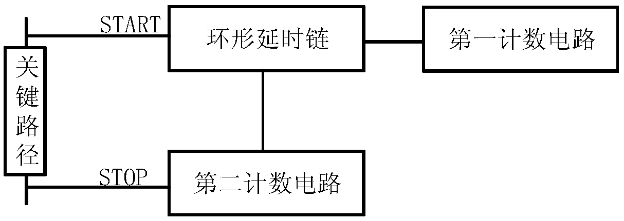
[0052] On the basis of Embodiment 1, please refer to the two-stage TDC circuit applied to process uncontrolled detection in this embodiment figure 2 , with figure 2 It is a structural block diagram of a first-stage circular delay chain TDC circuit according to an embodiment of the present invention. The first-stage annular delay chain TDC of the TDC circuit of the present invention comprises an annular delay chain, a first counting circuit and a second counting circuit; STATR and STOP signals are respectively used as the input of the annular delay chain and the second counting circuit, and The outputs of the delay chain are electrically connected to the first counting circuit and the second counting circuit respectively.
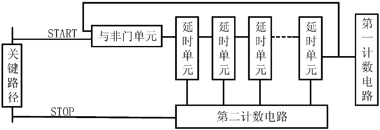
[0053] See image 3 , image 3 It is the structural refinement frame of the first-stage circular delay chain TDC circuit of the embodiment of the present invention Figure 1 . image 3 In , the circular delay chain is composed of a two-input NAND gate...
Embodiment 3
[0063] The two-stage TDC circuit applied to process uncontrolled detection in this embodiment is further described in detail on the time margin selection circuit and the second-stage vernier TDC circuit on the basis of the above embodiments.
[0064] See Figure 10 , Figure 10 It is a schematic diagram of the circuit structure of the time margin selection circuit of the two-stage TDC circuit of the present invention. The time margin selection circuit includes a delay unit group, an SEL decoding circuit and a multiplexer; wherein, the delay unit group is electrically connected to the first-stage circular delay chain TDC circuit and the multiplexer, and is used for starting from the first-stage circular The delay chain TDC circuit receives the remaining time margin information and delays the time margin information and sends it to the multiplexer for selection and output; the SEL decoding circuit is electrically connected to the first-stage circular delay chain TDC circuit and...
PUM
 Abstract
Description
Claims
Application Information
 - R&D
- Intellectual Property
- Life Sciences
- Materials
- Tech Scout
- Unparalleled Data Quality
- Higher Quality Content
- 60% Fewer Hallucinations
Browse by: Latest US Patents, China's latest patents, Technical Efficacy Thesaurus, Application Domain, Technology Topic, Popular Technical Reports.
© 2025 PatSnap. All rights reserved.Legal|Privacy policy|Modern Slavery Act Transparency Statement|Sitemap|About US| Contact US: help@patsnap.com