
High-pressure gas holder

A gas tank and high-voltage technology, applied in the field of gas tank, can solve the problems of high labor intensity, random placement, unsafe, etc., and achieve the effects of ensuring safe operation, improving the ability of balanced and stable operation, and enhancing the ability to mediate.

Pending Publication Date: 2019-04-16
WISDRI ENG & RES INC LTD
View PDF13 Cites 2 Cited by
  • Summary
  • Abstract
  • Description
  • Claims
  • Application Information

AI Technical Summary

Problems solved by technology

In reality, the adjustment of the placement position of the piston live counterweight is completed by manual handling, which is labor-intensive, the placement position is relatively random, the speed is slow and the effect of immediate deviation correction cannot be achieved, and the equal inclination angle of the piston surface is relatively large. It is not safe to move around, especially for thin oil sealed cabinets, the sealing oil spilled on the piston makes the working surface slippery, and accidents such as falling and live counterweight hitting the piston surface are easy to occur

Method used


Image

  • High-pressure gas holder
  • High-pressure gas holder
  • High-pressure gas holder

Examples


Embodiment 1

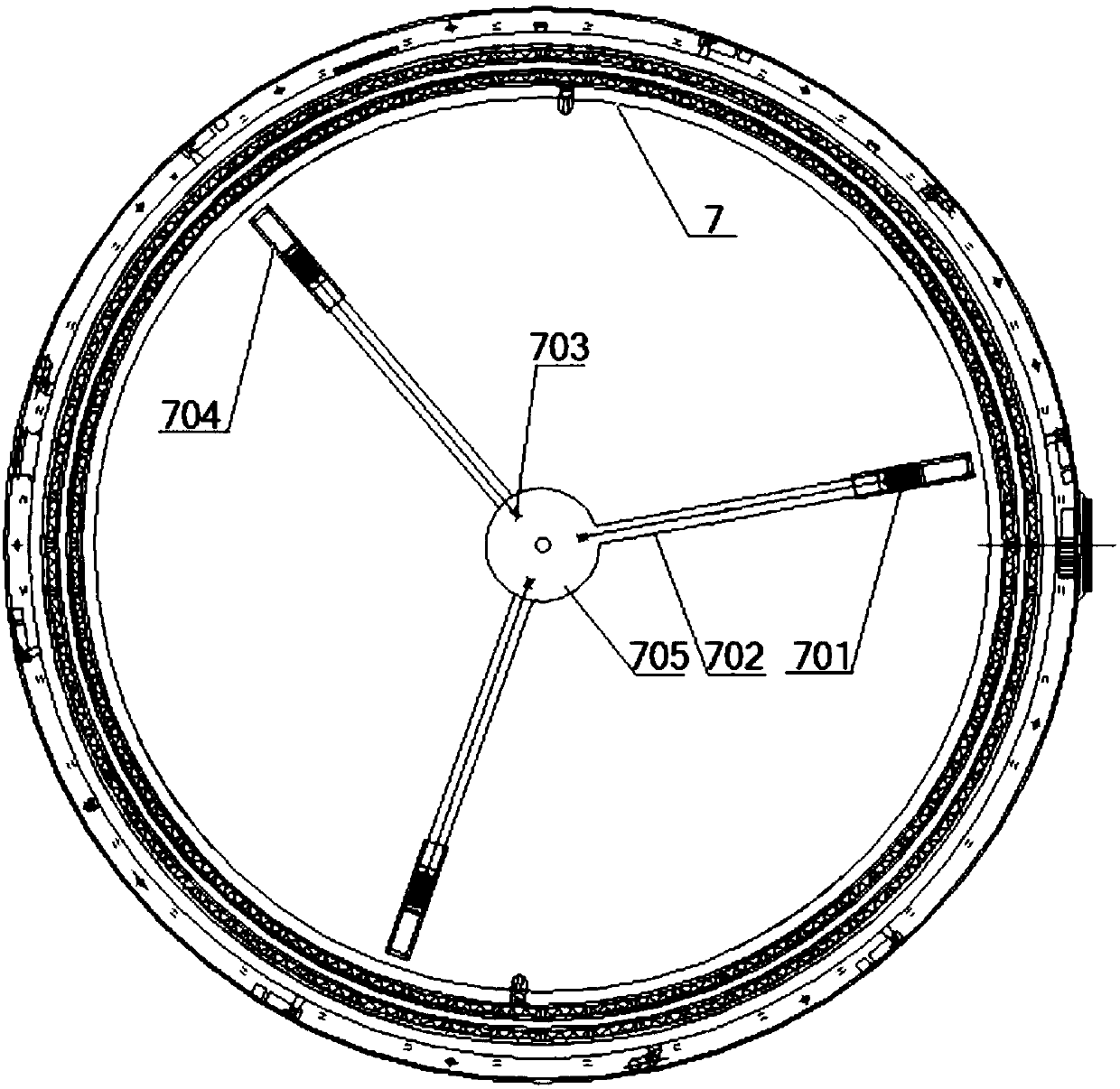
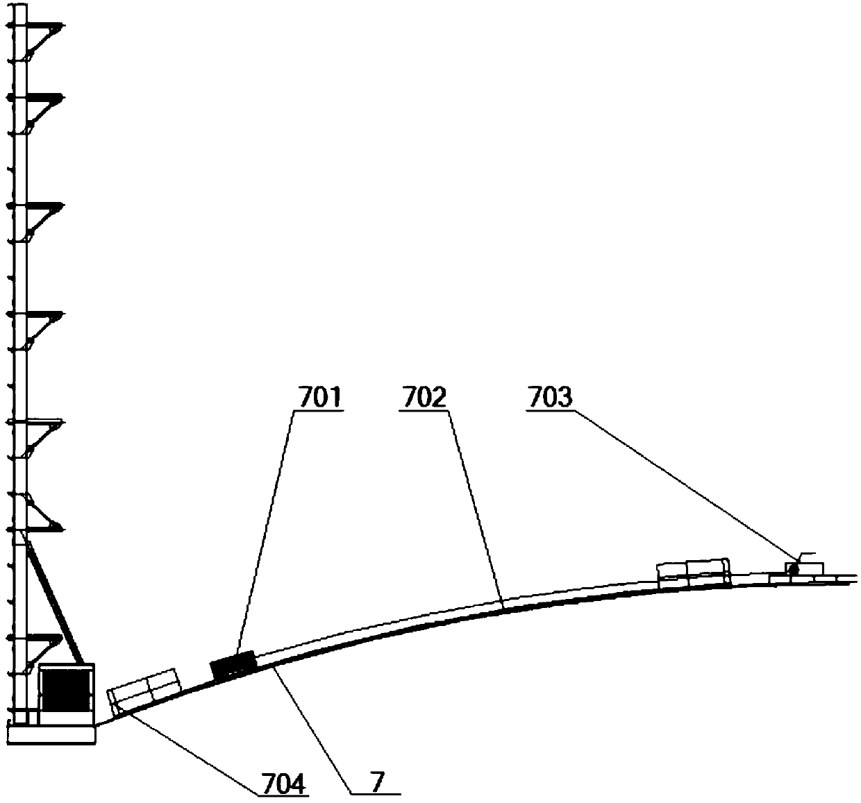
[0023] Such as figure 1 and figure 2 , the embodiment of the present invention provides a high-pressure gas cabinet, including a cabinet body and a piston 7 movably arranged in the cabinet body, a plurality of live counterweights 701 and a plurality of sliding guide rails 702 are arranged on the top of the piston 7, and the sliding The number of guide rails 702 is the same as that of the living counterweights 701 and they are arranged in one-to-one correspondence. Each of the living counterweights 701 is connected with a sliding drive mechanism 703 for driving them to slide on the corresponding sliding guide rails 702 .

[0024] The high-pressure gas cabinet provided in this embodiment drives the live counterweight 701 to slide on the piston 7 through the sliding drive mechanism 703, quickly and conveniently adjusts the position of the live counterweight 701, effectively improves the balanced and stable operation ability of the piston 7, and makes the high-pressure The skew ...

Embodiment 2

[0032] This embodiment provides a high-pressure gas cabinet, which is further optimized for the high-pressure gas cabinet provided in the above-mentioned embodiments. The high-pressure gas tank is a double-stage gas tank.

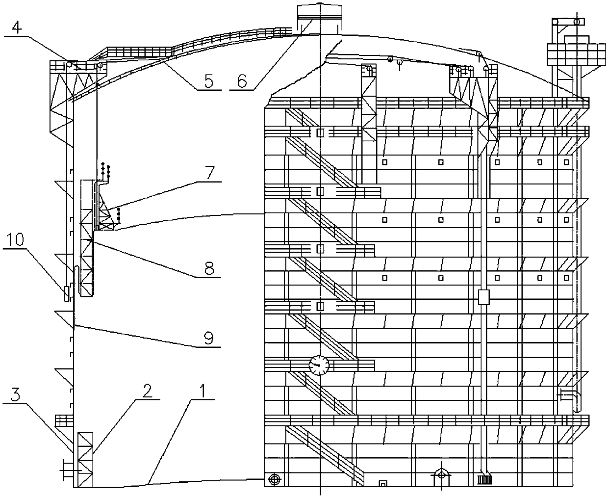
[0033] image 3 Shown is a schematic structural diagram of a traditional double-stage rubber membrane sealed dry-type gas cabinet. Generally, the cabinet body includes a cabinet bottom plate 1, a cabinet top plate 5 and side plates 3, and a piston 7 and a T baffle 8 are arranged inside the cabinet. Both the piston 7 and the T baffle 8 can move up and down in the cabinet; during the operation of the gas cabinet, the gas enters and exits by moving the piston 7 and the T baffle 8 up and down. When the T baffle 8 is not in contact with the piston 7 , supported by the T baffle bracket 2, after the piston 7 rises to contact with the T baffle 8, the T baffle 8 can be lifted to separate from the T baffle bracket 2; During the activity, there is a rubber membrane ...


PUM


Abstract

The invention relates to a high-pressure gas holder comprising a holder body and a piston movably arranged in the holder body. Multiple movable balance weights are arranged on the top of the piston. Multiple sliding guide rails are further arranged on the top of the piston. The number of the sliding guide rails is the same as that of the movable balance weights, and the sliding guide rails and themovable balance weights are arranged in a one-to-one correspondence manner. Each movable balance weight is connected with a slippage drive mechanism used for driving the movable balance weight to slip on the corresponding sliding guide rail. According to the high-pressure gas holder, by driving the movable balance weights by the slippage drive mechanisms to slide on the piston, the positions of the movable balance weights are rapidly and conveniently regulated, and the balanced and stable operation capacity of the piston is effectively improved; and therefore the piston skewing regulation capacity of the high-pressure gas holder can be remarkably enhanced, safe operation of the gas holder is ensured, the manual operation strength is lowered, and operation safety of personnel is ensured.

Description

technical field [0001] The invention belongs to the technical field of gas cabinets, and in particular relates to a high-pressure gas cabinet. Background technique [0002] Gas holders are widely used in the storage of industrial and civil gas, which realizes the throughput of gas through the up and down movement of the piston in the gas holder. Gas cabinets with high gas storage pressure (such as gas cabinets with gas storage pressure greater than or equal to 10kPa) are more and more popular and widely used because of their simple gas treatment process, energy saving and environmental protection, and suitable for large industrial enterprises. . But it is also because of its high gas storage pressure, which means that its piston weight needs to be larger. At the same time, during operation, the piston is in a state of sliding up and down or even floating, and its balance adjustment is very critical and difficult. . [0003] For high-pressure gas holders, in order to achie...

Claims


Application Information

Patent Timeline
Patent Type & Authority Applications(China)
IPC IPC(8): F17B1/14F17B1/02
CPCF17B1/02F17B1/14
Inventor 付重重
Owner WISDRI ENG & RES INC LTD
Learn More