Chisel holder

A technology of holder and chisel, which is used in roads, slitting machinery, construction, etc., can solve the problems of increased wear of the disc and chisel holder, and achieve the effect of improving the sealing effect.

Active Publication Date: 2019-04-16
WIRTGEN GMBH
View PDF10 Cites 2 Cited by
  • Summary
  • Abstract
  • Description
  • Claims
  • Application Information

AI Technical Summary

Problems solved by technology

This leads to increased wear of the disc and the bit holder, especially at high lateral forces acting on the bit

Method used


Image

  • Chisel holder
  • Chisel holder
  • Chisel holder

Examples


Embodiment Construction

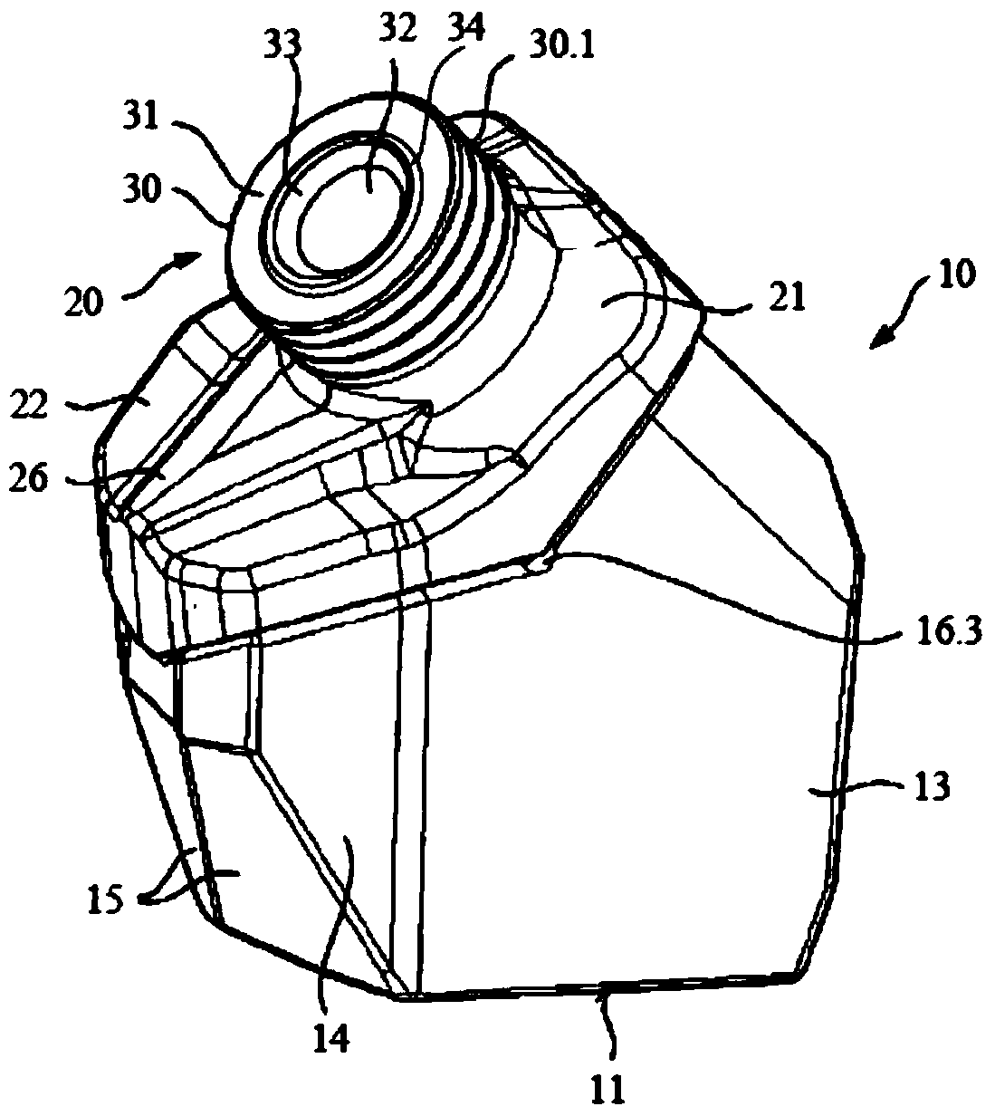
[0031] figure 1 A bit holder 20 detachably connected to the base frame 10 is shown in a perspective side view. Opposite the bit holder 20 , the base frame 10 is closed by a concavely formed lower closure side 11 . The base frame 10 is fastened with this closed side 11 to a not shown milling drum of a ground working machine (here a milling machine). In order to be able to transmit high forces, the chassis 10 is preferably welded to the milling drum. The base body 13 of the base frame 10 has at the front in the working direction two inclined surfaces 15 arranged at an angle symmetrical to one another with respect to the longitudinal center plane of the base frame 10 . Connected to this lateral slope are two inclined surfaces 14 arranged in mirror-symmetrical angle with respect to the longitudinal median plane of the undercarriage 10 , only one of which is visible in this perspective view. The inclined surface 14 merges at an angle into the side of the base body 13 . The side...


PUM


Abstract

The invention relates to a chisel holder for a ground working machine, in particular a milling machine, comprising a support body, on which a holding section of a chisel receptacle is moulded, and a plug-in fitting is moulded in relation to the holding section. At the end side, the holding section is closed by a wear surface and the chisel receptacle is closed by a centering receptacle which is open in a chamfered manner towards a wear surface. A centering height, measured in the direction of the longitudinal center axis, which extends between an end of the centering receptacle facing away from the wear surface and a maximum point of a projection projecting beyond the wear surface, is designed in such a way that the ratio between the inside diameter Di of the chisel receptacle and the centering height is less than 8; and / or that the centering height is greater than an axial play of a round-shank chisel installed in the chisel holder; and that the support body comprises at least two cutting surfaces forming cutting surface pairs on its side facing away from the holding portion, and the cutting surfaces form an angle. Reduced wear on the holding portion of the chisel holder and a reduced load on the insertion projection, and thus an extension of the service life of the chisel holder, are achieved.

Description

technical field [0001] The invention relates to a chisel holder for ground working machines, in particular milling machines, the chisel holder having a support body on which a holding section is molded in the region of the processing side, in which holding section A chisel receptacle for accommodating the shank of a round-shank chisel is formed in the middle, wherein the holding section is closed at its end facing away from the support body by a wear surface surrounding the chisel receptacle for abutment against the Round shank chisel or support element, wherein the chisel receptacle transitions indirectly or directly into the wear surface via a centering surface of the centering receptacle which is inclined to the longitudinal center axis of the chisel receptacle Oriented, and on the side opposite to the holding section, a plug-in attachment is molded for fixing the chisel holder to the chassis on the support body. Background technique [0002] Use a ground machine to carr...

Claims


Application Information

Patent Timeline
Patent Type & Authority Applications(China)
IPC IPC(8): E01C23/088
CPCE01C23/088E21C35/18E21C35/19E21C35/197E21C35/191B28D1/188E21C35/1933
Inventor K·布尔尔A·约斯特T·莱纳特
Owner WIRTGEN GMBH
Why Eureka
Try Eureka