Material feeding amount control device and method applied to die cutting machine

A technology of a control device and a control method, which is applied in the directions of positioning objects, thin material handling, transportation and packaging, etc. It can solve the problems that the feeding accuracy cannot meet the needs of production, achieve smooth and clear marking boundaries, improve feeding accuracy, and eliminate errors effect of factors

Active Publication Date: 2019-04-16
无锡市正先自动化设备有限公司
View PDF8 Cites 1 Cited by
  • Summary
  • Abstract
  • Description
  • Claims
  • Application Information

AI Technical Summary

Problems solved by technology

However, with the improvement of product quality, the precision requirements of products are getting higher and higher, resulting in the feeding accuracy of the traditional feeding mode can no longer meet the needs of production

Method used


Image

  • Material feeding amount control device and method applied to die cutting machine
  • Material feeding amount control device and method applied to die cutting machine
  • Material feeding amount control device and method applied to die cutting machine

Examples


Embodiment 1

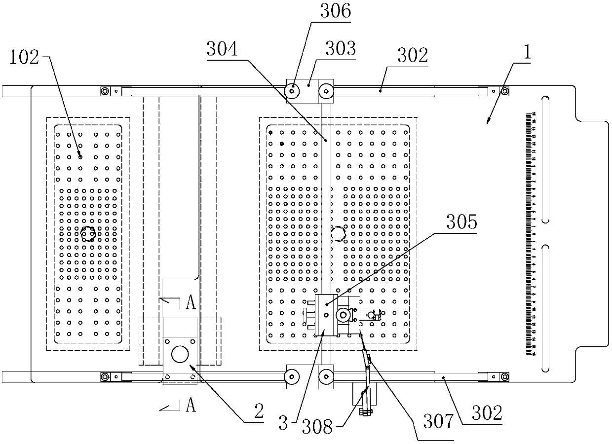
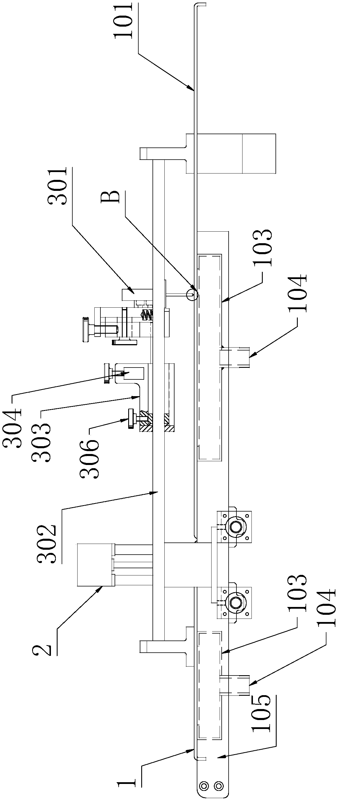
[0039] like figure 1The shown feed positioning device applied to a die-cutting machine includes a marking mechanism 2 arranged on a feeding platform 1 of a die-cutting machine and a marking mechanism 3 located downstream of the marking mechanism 2. The marking mechanism 2 The relative position of the marking mechanism 3 can be adjusted, the marking mechanism 2 can mark the film-type material, and the marking mechanism 3 detects the mark downstream.

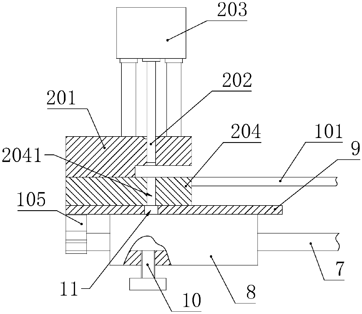
[0040] to combine figure 1 and figure 2 As shown, the marking mechanism 2 includes a punch frame 201 arranged on one side of the feeding platform 1, a punch 202, a driving device 203 for driving the punch 202 to punch materials, and a 1, the stamping die 204 matched with the punch 202, the driving device 203 is an air cylinder, fixedly connected on the punch frame 201, and the punch 202 is connected with the driving device 203 through transmission. In this embodiment, the side of the cross-section of the punch 202 close to the...

Embodiment 2

[0059] A method for controlling the feed rate of a die-cutting machine, comprising the following specific steps:

[0060] a. If Figure 8 As shown, a fixed position is set on the feeding platform 1 upstream of the molding system 4, and a marking mechanism 2 is installed to punch out marks on the material;

[0061] b. Set a fixed detection position between the molding system 4 and the marking mechanism 2 according to the material feeding distance requirements, and install the standard detection mechanism 3 to detect the marks on the material;

[0062] c. Control the feed of materials according to the detection results. When the mark detection mechanism 3 at the detection position detects the mark, stop the material feed, indicating that the feed amount reaches the requirement of the material feed distance, and the mark detection mechanism 3 at the detection position detects the mark. The mark is used as the basis, and the material is punched; while the material is punched, the...


PUM


Abstract

The invention relates to a material feeding amount control device and method applied to a die cutting machine. Thematerial feeding amount control device comprises a marking mechanism disposed on a feeding platform of the die cutting machine and a mark inspection mechanism located downstream of the marking mechanism. The relative position of the marking mechanism and the mark inspection mechanism can be adjusted, the marking mechanism can mark a film type material, and the mark inspection mechanism detects marks downstream.The control method includes the steps that a, the material is positionedand marked upstream of a die pressing system; b, the marks on the material aredetected upstream of the die pressing system; c, material feeding isstopped when the marks are detected, and then the material is simultaneously punched, position and marked; and d,after punching of the material is completed, the material feeding isstarted again, and then the steps b and c areconducted again until the material is all punched. The marking mechanism and the mark inspection mechanism are used for controlling the feeding amount of the diecutting machine for each die pressing, thereby improving the feeding precision of the diecutting machine.

Description

Technical field: [0001] The invention belongs to the technical field of die-cutting machines, and in particular relates to a material feed control device and a control method applied to a die-cutting machine. Background technique: [0002] The die-cutting machine is mainly used for full-cut or half-cut die-cutting, indentation and bronzing operations of some non-metallic materials, self-adhesive, EVA, double-sided adhesive tape, mobile phone pads, etc. Cut out a certain shape. [0003] In order to improve mechanical automation, the current die-cutting machine usually performs die-cutting on the coiled material, and the coiled material is fed into the mold for die-cutting through the extrusion and traction of the feeding roller. In order to improve the feeding accuracy, a servo motor is usually used to drive the feeding The roller uses the high precision of the servo motor to control the high-precision rotation of the feeding roller, so as to accurately control the feeding l...

Claims


Application Information

Patent Timeline
Patent Type & Authority Applications(China)
IPC IPC(8): B65H9/00
CPCB65H9/00
Inventor 王己衣荣伟洪
Owner 无锡市正先自动化设备有限公司
Why Eureka
Try Eureka