
A two-way pressure relief valve

A technology of pressure relief valve and pressure relief valve, which is applied in the direction of valve devices, safety valves, balance valves, etc., can solve the problems of difficult pressure relief capacity to meet demand, slow pressure relief protection, inconvenient performance adjustment, etc., to achieve wide applicability, The effect of gentle water hammer pressure and simple structure

Active Publication Date: 2020-07-17
HOHAI UNIV
View PDF8 Cites 2 Cited by
  • Summary
  • Abstract
  • Description
  • Claims
  • Application Information

AI Technical Summary

Problems solved by technology

Usually there are complex systems, many hidden troubles, inconvenient performance adjustment, slow pressure relief protection, etc.
Moreover, traditional pressure relief valves are often limited by unfavorable conditions such as processing technology restrictions, and the pressure relief capacity is difficult to meet the demand

Method used


Image

  • A two-way pressure relief valve
  • A two-way pressure relief valve
  • A two-way pressure relief valve

Examples


Embodiment Construction

[0023] The present invention will be specifically introduced below in conjunction with the accompanying drawings and specific embodiments.

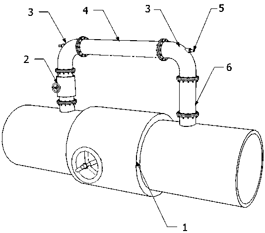
[0024] Such as figure 1 As shown, a two-way pressure relief valve of the present invention is connected in parallel with a series branch valve 2 and a branch pipe 6 of a decompression chamber 4 at both ends of the main valve 1 of the main pipeline.

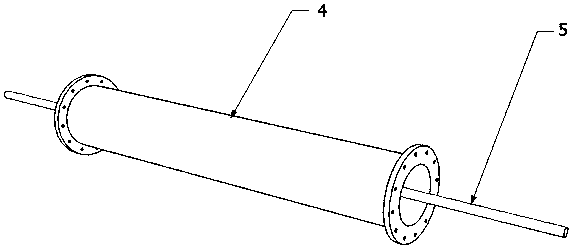
[0025] The decompression chamber 4 of this implementation is a section of pipeline of the branch pipeline 6, which is arranged in parallel with the main pipeline; the two ends of the decompression chamber 4 are vertically connected to the main pipeline through the elbow 3, and the branch valve 2 is connected in series on the vertical pipeline .

[0026] The chamber body cavity of the decompression chamber 4 is provided with a coaxial screw rod 5, and the two ends of the screw rod 5 are respectively screwed to the screw holes on the elbow 3, and the elbow 3 is revealed, and the screw holes ar...


PUM


Abstract

The invention discloses a two-way pressure relief valve. A branch pipeline with a branch valve is arranged on a main pipeline, wherein the branch pipeline is connected in parallel with a main valve, and a pressure reducing bin with a plurality of pressure reducing valve blocks are connected in series in the branch pipeline. By arranging the pressure relief branch pipeline connected in parallel with the main pipeline, auxiliary two-way pressure relief and flat pressing functions are realized after the main pipeline is closed. Through the pressure reducing bin connected in series in the branch pipeline, the buffer pressure reducing effect is achieved. Through the flexible pressure reducing valve blocks, certain deformation is generated when the two-way pressure relief valve is impacted by pressure to support liquid discharging. By adjusting the number of pressure reducing valve blocks, the working pressure of the pressure reducing bin can be adjusted. Through the different spacing between the pressure reducing valve blocks, the pressure can be reduced differentially in a progressive mode. Compared with an existing pressure relief valve, the two-way pressure relief valve has the simple structure, small size, small use limit and high reliability, can effectively reduce and smooth the bidirectional surge pressure in a transportation pipeline, and has high practicability and wide applicability.

Description

technical field [0001] The invention relates to a pressure relief valve, in particular to a two-way pressure relief valve, which belongs to the technical field of water conservancy engineering. Background technique [0002] With the progress of society and the development of urbanization, more and more gases and liquids need to be transported through pipelines, such as urban water supply pipelines, water diversion pipes of hydropower stations, oil and natural gas pipelines, etc. [0003] Long-distance pipeline transportation often needs to close the main valve when the working conditions change. When the main valve is closed, the upstream and downstream pressure will fluctuate violently, in order to protect the pipeline and related equipment, the pressure relief valve was born due to this situation. However, traditional safety pressure relief valves are usually composed of spring direct opening or main safety valves, impulse valves, and inlet and outlet signal piping system...

Claims


Application Information

Patent Timeline
Patent Type & Authority Patents(China)
IPC IPC(8): F16K17/02
CPCF16K17/02
Inventor 林伟刘道桦甄向荣周冰逸郭兰波朱岑蔡付林周建旭
Owner HOHAI UNIV
Learn More