Sliding bearing with aligning function

A sliding bearing and self-aligning technology, which is applied in the direction of sliding contact bearings, rotating bearings, bearings, etc., can solve the problems of poor adaptability to roller shaft load changes and low service life of sliding bearings, so as to improve the working condition of swing fit and improve Effect of service life and prolonging service life

Pending Publication Date: 2019-04-12
CHENGDU LEEJUN IND +1
View PDF23 Cites 5 Cited by
  • Summary
  • Abstract
  • Description
  • Claims
  • Application Information

AI Technical Summary

Problems solved by technology

[0008] Although the second-generation spherical self-aligning sliding bearing developed by the applicant has solved the problem that the first-generation product cannot meet the load-bearing environment with more and more complicated working conditions of the roller shaft, and the service life of the sliding bearing is low, etc., but because it is still used Wrap angle design less than or equal to 180° (facilitating installation), the angle parameter of the inclined arrangement of the spherical tile and the concave spherical seat can only be arbitrarily selected between 15°-45°, the angle parameter α of the inclined arrangement of the spherical tile and the concave spherical seat is actual Corresponding to the load-bearing area of ​​the bearing pad, the larger the value of α, the larger the load-bearing area of ​​the bearing pad, and the stronger the adaptability of the bearing pad to the change of the direction of the resultant force it bears, but the parameter range of 15°-45° cannot fully meet the requirements. , the structure based on the second-generation spherical self-aligning sliding bearing can no longer expand the parameter range of α. As a result, although the second-generation sliding bearing can bear the load evenly, its adaptability to the change of the roller shaft load is still poor

Method used


Image

  • Sliding bearing with aligning function
  • Sliding bearing with aligning function
  • Sliding bearing with aligning function

Examples


Embodiment 1

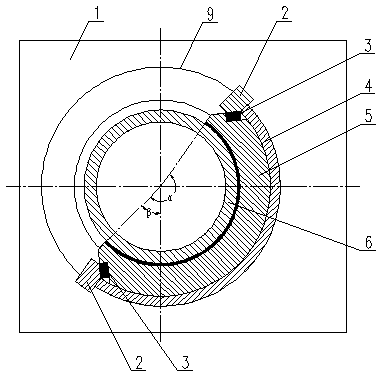
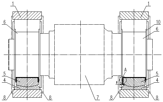
[0052] like Figure 1-4 As shown, a CLM260160 adjustable center sliding bearing for the rotating shaft of a high-pressure roller mill. The rotating shaft 7 includes a driving end and a floating end. The journal speed of the rotating shaft 7 is ≤1.5m / s, and the journal pressure is ≤25MPa. The central sliding bearing includes a bearing seat 1, which is used to fit the sleeve 6 at the journal of the rotating shaft 7. The outer surface of the sleeve 6 is placed in the inner surface of the spherical pad 5 to form a circumferential sliding friction pair. The spherical pad The outer surface of 5 protrudes outward to form an outer spherical surface, forming the outer spherical surface of spherical tile 5. The arc surface forms the outer circular surface of the spherical seat 4, the outer spherical surface of the spherical shoe 5 is in contact with the inner spherical surface of the spherical seat 4 to form a rolling friction pair relationship, and the spherical seat 4 is installed in ...


PUM


Abstract

The invention discloses a sliding bearing with an aligning function. The bearing comprises a shaft sleeve and a spherical tile which forms a circumferential sliding friction pair with the shaft sleeve, wherein the angle range of the spherical tile is 180-270 degrees, the opening end below the spherical tile is connected with a center, the included angle of a vertical central line is 30-90 degrees,the spherical tile is installed in a spherical seat, the spherical seat is installed in a bearing hole of a bearing block, in the bearing hole, the two ends of an opening of the spherical seat are both provided with stop blocks used for limiting the spherical seat to move in the circumferential direction, the two ends of the opening of the spherical tile are both fixedly provided with top blocks,the top blocks are in line contact with the stop blocks, a sliding friction pair is formed by the stop blocks and the top blocks, the surfaces of the top blocks which are in contact with the stop blocks are sliding surfaces, and on the surface of the end surface of the shaft sleeve is plane, center lines of the sliding surfaces of the two top blocks are perpendicular to each other. According to the spherical sliding bearing with the aligning function, not only all the advantages of an existing sliding bearing are achieved, but also the advantages of being simple in manufacturing and processing, low in cost, long in service life and the like are also achieved, larger loads can be borne, lower rotating speeds is achieved, so that equipment upsizing is not restricted by the bearing.

Description

technical field [0001] The invention relates to the field of sliding bearings, in particular to an adjustable centering sliding bearing for supporting a rotating shaft. Background technique [0002] The main shaft of heavy machinery is usually a low-speed and heavy-duty working shaft. The linear speed of the journal is usually below 5m / s, and the pressure of the journal is greater than 10MPa. Rolling bearings or sliding bearings have been used for support for a long time. Rolling bearings mostly use self-aligning roller bearings, four-row roller bearings, etc. During use, accidents such as roller fracturing, inner ring fracturing, and cage fracturing often occur, and with the development of large-scale equipment, such as ball mills, Roller presses, high-pressure roller mills, etc. are being enlarged, and the linear speed of the journal is often lower and the pressure of the journal is higher, which requires larger rolling bearings, and the manufacturing materials and process...

Claims


Application Information

Patent Timeline
Patent Type & Authority Applications(China)
IPC IPC(8): F16C23/04F16C33/04
CPCF16C23/043F16C33/04
Inventor 何亚民魏勇徐智平
Owner CHENGDU LEEJUN IND
Why Eureka
Try Eureka