Cooling body with regulator

A regulator and cooling body technology, applied in the direction of glass manufacturing equipment, manufacturing tools, etc., can solve the problems of affecting the moving distance of movable parts, affecting the service life of the bushing plate, and large shaking space, so as to improve product quality and production stability. The effect of improving the distance of movement and improving work efficiency

Inactive Publication Date: 2019-04-12
LINZHOU GUANGYUAN NEW MATERIAL TECH
View PDF5 Cites 0 Cited by
  • Summary
  • Abstract
  • Description
  • Claims
  • Application Information

AI Technical Summary

Problems solved by technology

[0008] Aiming at the deficiencies of the prior art, the present invention provides a cooling body with a regulator, which solves the problem of large sloshing space, there is no space reserved for the spring at the spring, and the contracted position of the spring affects the moving distance of the movable part The problem and the shaking of the cooling body due to the operation of the staff during the adjustment process will cause the temperature fluctuation of the entire bushing plate and local temperature fluctuations. The contact between the oxide on the cooling body and the leak nozzle will cause the temperature difference of the leak nozzle and make the operation difficult, which will affect the use of the bushing plate Lifespan, unable to accurately judge abnormal items such as adjustment results

Method used


Image

  • Cooling body with regulator
  • Cooling body with regulator
  • Cooling body with regulator

Examples


Embodiment 1

[0047] Take the four-point pull cooler as an example, such as Figure 4 shown.

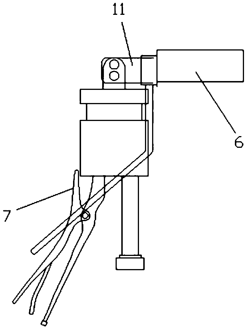
[0048] There are 13 cooling fins drawn in four quarters, and the specifications are length*width*height=55*20*2, and they are uniformly fixed on one side of the bar block on the cooler, and the water inlet and outlet pipes are set at both ends of the bar block. There is a through hole in the middle of the strip block, which communicates with the water inlet pipe and the water outlet pipe, allowing cooling water to pass through. The cooling fins 6 are arranged in parallel, and two connecting pieces 11 are fixed below the strip block, and two bolts are arranged on the connecting piece 11 hole.

Embodiment 2

[0050] Take the eight-point pull cooler as an example, such as Figure 5 shown.

[0051] There are 12 pieces of cooling fins in the Bafen pull, and the specifications are length*width*height=50*20*1.3, and they are evenly fixed on one side of the bar block on the cooler, and the water inlet and outlet pipes are set at both ends of the bar block. There is a through hole in the middle of the strip block, which communicates with the water inlet pipe and the water outlet pipe, allowing cooling water to pass through. The cooling fins 6 are arranged in parallel, and two connecting pieces 11 are fixed below the strip block, and two bolts are arranged on the connecting piece 11 hole.

Embodiment 3

[0053] Take Shifenla cooler as an example, such as Figure 6 shown.

[0054] There are 6 cooling fins that are very stretched, and the specifications are length*width*height=85*20*1.0, and they are evenly fixed on one side of the bar block on the cooler. There is a through hole in the middle of the shaped block, which communicates with the water inlet pipe and the water outlet pipe, so that cooling water can pass through. The cooling fins 6 are arranged in parallel, and two connecting pieces 11 are fixed under the strip block, and two bolt holes are opened on the connecting piece 11. .


PUM


Abstract

The invention relates to a cooling body with a regulator, which comprises a cooler, a regulator and a rectangular plate. The cooler comprises a strip-shaped block, wherein one side of the strip-shapedblock is fixedly provided with a cooling fin, a channel is arranged in the strip-shaped block, and two ends of the strip-shaped block are respectively provided with a water inlet pipe and a water outlet pipe. The regulator comprises a fixed block, wherein a screw rod through hole is arranged in the middle, and a screw rod penetrates through the screw rod through hole. Blade grooves are symmetrically arranged at two sides of the fixed block, and a nipper mouth hole is arranged between the two blade grooves on the fixed block. The rectangular plate is arranged above the fixed block. Blade holesare arranged at the position corresponding to the blade grooves of the fixed block, blades are arranged at the position corresponding to the blade holes, and a clamping hole is arranged on the fixedblock. A connecting piece enables the cooler to be connected with the regulator through the matching of a connecting block and a connecting slice. According to the cooling body with the regulator, themovable part and the fixed part of the regulator are fully-buckled sliding chutes, with an extremely small shaking space, which ensures that the shaking of the cooler is reduced in the adjusting process, the speed is more uniform in the adjusting process, the adjustment of staff is facilitated, and the product quality and the production stability are improved.

Description

technical field [0001] The invention relates to a cooling part of electronic yarn drawing equipment, in particular to a cooling body with a regulator. Background technique [0002] The cooling body is an important part to control the temperature of the drain plate and make the high-temperature glass liquid rapidly cool and form in the drawing process of the glass fiber tank kiln. The cooling body is arranged under the leaking plate, and the cooling water enters through the water inlet pipe, passes through the cooling fins arranged in the gap of the leaking nozzle of the leaking plate, and then flows out from the outlet pipe to play the role of cooling. [0003] During the wire drawing process, the molten glass flows into the bushing plate, which is adjusted to a suitable temperature, then flows out through the nozzle, and is stretched into continuous glass fibers by the wire drawing machine at the outlet. After the high-temperature viscous glass liquid flows out of the bushi...

Claims


Application Information

Patent Timeline
Patent Type & Authority Applications(China)
IPC IPC(8): C03B37/08
CPCC03B37/08
Inventor 李伟余启辉卢皓张斌
Owner LINZHOU GUANGYUAN NEW MATERIAL TECH
Why Eureka
Try Eureka