
Member for unmanned rotorcraft and method

A technology for unmanned rotors and components, which is applied to aircraft parts, wings, ground devices, etc., can solve the problems of unfavorable distribution of speed message information, low operational performance, low utilization of the rotating shaft and the output shaft of the rotating speed, etc., to achieve The effect of reducing mobile communication bandwidth and improving performance

Inactive Publication Date: 2019-04-12
西安智星语知识产权服务有限公司
View PDF1 Cites 0 Cited by
  • Summary
  • Abstract
  • Description
  • Claims
  • Application Information

AI Technical Summary

Problems solved by technology

[0018] In order to solve the above-mentioned problems, the present invention provides a component and its method for a rotary-wing unmanned aerial vehicle, which effectively avoids the strong adhesive bonding and welding structure in the prior art that is not conducive to disassembly and cannot be repeatedly disassembled for use. The utilization rate of the rotating shaft and the output shaft of the rotating speed is not high, and the operation of hoop hooping is complicated during assembly, disassembly, and maintenance of the rotating shaft and the output shaft of the rotating speed, so that the corresponding operation performance is not high, and the capacity of distributing the rotating speed message information is not small Occasionally, it will use a lot of bandwidth, which is not conducive to the defect that the mobile communication module distributes the speed message information between two mobile communication modules.

Method used


Image

  • Member for unmanned rotorcraft and method
  • Member for unmanned rotorcraft and method
  • Member for unmanned rotorcraft and method

Examples


Embodiment Construction

[0064] The present invention will be further described below in conjunction with the accompanying drawings and embodiments.

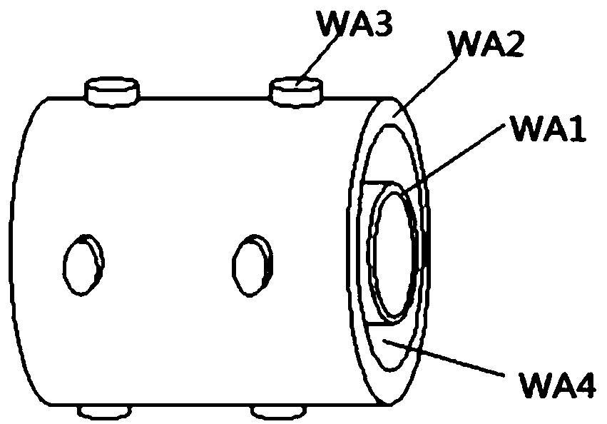
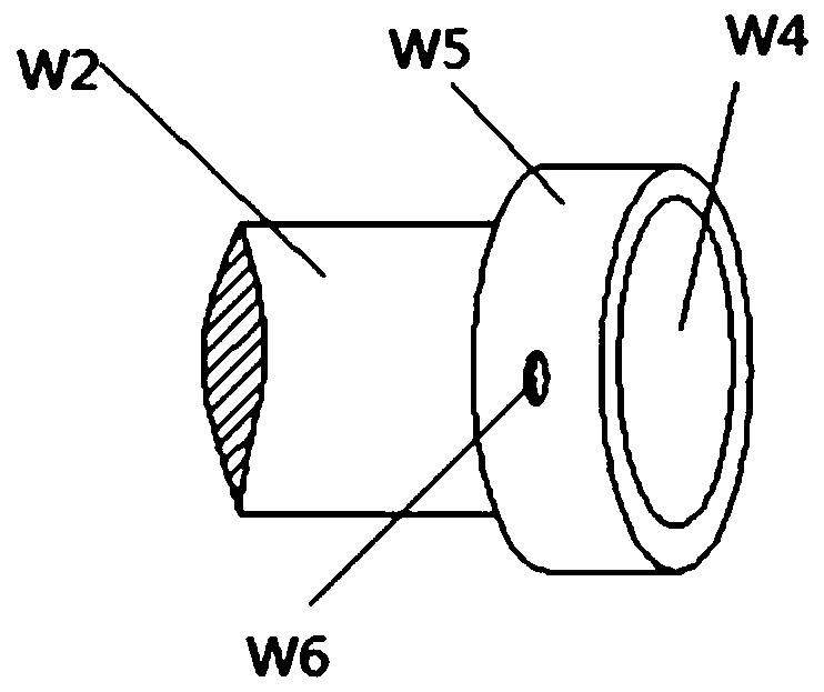
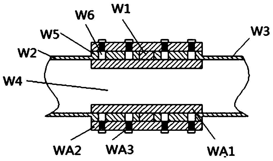
[0065] Such as Figure 1-Figure 3 As shown, the components used for the rotor drone include the rotor drone described in the application number "201720802053.4", the application date is "2017.07.04" and the patent name is "rotor drone";

[0066] The rotor UAV includes a fuselage main body, a wing arranged on the fuselage main body, and a power assembly arranged on the wing; the power assembly includes a motor, a propeller connected to the output shaft of the motor, and a protective shield arranged on the periphery of the motor. Part; the protective part is located at least partially above the motor, and the protective part is used to protect the motor.

[0067] The protective component includes a protective umbrella, which is located between the propeller and the motor and is connected to the output shaft. When the output shaft rotates, the protective ...


PUM


Abstract

The invention discloses a member for an unmanned rotorcraft and a method, a propeller comprises a rotating shaft and blades, a plurality of blades are welded on the rotating shaft, the rotating shaftis connected with an output shaft of a motor through a coupling part; a revolving speed message information transmitted from a processor is obtained,; the revolving speed message information is wholeinformation, the whole information comprises information needed for acquiring the device; the member for the unmanned rotorcraft effectively avoids the defects in the prior art that: the use ratios ofthe rotating shaft and the output shaft of the motor are not high as a framework adhered and welded by a strong adhesive is not beneficial for decomposing and cannot be repeatedly decomposed and used, the corresponding operating performance is not high as the operations of assembling and decomposing in the coupling of a garter spring and the operations of maintaining the rotating shaft and the output shaft of the motor are complicated, and using considerable bandwidth when the capacity for distributing the revolving speed message information is not small is not beneficial for distributing therevolving speed message information among a plurality of mobile communication modules II by a mobile communication modules I.

Description

technical field [0001] The invention relates to the technical field of rotor drones, in particular to a component for rotor drones and a method thereof. Background technique [0002] Due to the advantages of maneuverability and stable flight of rotor UAVs, rotor UAVs are also used in commercial logistics transportation systems for mounting, transporting and delivering items. The top of the motor casing of a traditional rotor UAV is usually designed as a hollow structure to facilitate internal heat dissipation of the motor in a running state and avoid overheating of the motor. However, external impurities will enter into the motor through the hollow structure, thereby causing adverse effects on the motor, and in serious cases, causing the motor to fail to operate normally. [0003] As a result, the rotor drone described in the application number "201720802053.4", the application date "2017.07.04" and the patent name "rotor drone" was developed; [0004] The rotor UAV includ...

Claims


Application Information

Patent Timeline
Patent Type & Authority Applications(China)
IPC IPC(8): B64C3/32B64D47/02B64F1/00
CPCB64C3/32B64D47/02B64F1/00
Inventor 不公告发明人
Owner 西安智星语知识产权服务有限公司
Learn More