
A hydraulic cylinder inner wall cleaner

A technology for hydraulic cylinders and cleaners is applied in the field of cleaners and inner wall cleaners of hydraulic cylinders. Effect

Active Publication Date: 2021-10-08
钱俊
View PDF18 Cites 0 Cited by
  • Summary
  • Abstract
  • Description
  • Claims
  • Application Information

AI Technical Summary

Problems solved by technology

[0002] At present, when maintaining hydraulic components, most of the hydraulic cylinders are caused by wear on the sealing ring. Due to reciprocating motion friction, the gap between the sealing ring and the cylinder wall becomes larger, which in turn affects the stability of the hydraulic support. Therefore, during maintenance, it is usually necessary to disassemble the hydraulic cylinder, and then replace the sealing ring on the piston. Before disassembly and assembly, the inner wall of the hydraulic cylinder needs to be cleaned. The existing non-woven fabrics Wipe directly to clean the foreign matter on the inner wall of the cylinder, but in the cleaning process, it is necessary to cooperate with the cleaning solution, and use the non-woven cloth to dip the cleaning solution to wipe, but the operation is complicated, time-consuming and labor-intensive, and the efficiency is low, and it is directly connected to the cylinder by manpower. Contact wiping will scratch the inner wall of the cylinder and affect the sealing between the piston and the cylinder wall. High-pressure flushing is also used, but the impurities contained in the water quality directly hit the cylinder wall during flushing, affecting the quality of the cylinder wall , the above-mentioned cleaning solutions need to be pre-configured and mixed, and cannot be recycled after cleaning
[0003] Publication No. CN107228014A discloses a cylinder cleaning tool, which includes a connecting rod, a guide rod, a handle, a limit block, a blocking block and a positioning pin. One end of the connecting rod is connected to the guide rod, and the other end is connected to the handle. A plurality of limiting blocks are installed on the connecting rod, each of the limiting blocks is equipped with a blocking block, and the positioning pin is installed on the blocking block closest to the handle, and the invention passes through the pin hole Clean the cylinder, but it cannot clean the circumference at the same time, and it will contact the inner wall during cleaning, which is easy to cause scratches

Method used


Image

  • A hydraulic cylinder inner wall cleaner
  • A hydraulic cylinder inner wall cleaner
  • A hydraulic cylinder inner wall cleaner

Examples


Embodiment Construction

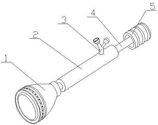
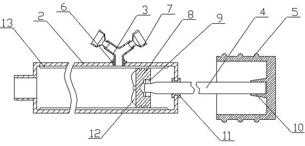
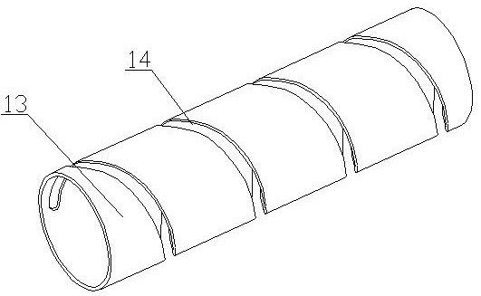
[0018] A hydraulic cylinder inner wall cleaner of the present invention is realized as follows: a hydraulic cylinder inner wall cleaner of the present invention consists of a cleaning shell (1), a hollow pipe (2), a connecting pipe (3), a piston rod (4), Handle (5), connecting rubber sleeve (6), connecting screw sleeve (7), piston (8), bearing (9), clamping sleeve (10), sealing ring (11), vane (12), inner guide sleeve (13), thread groove (14), filter plug (15), diverter block (16), rubber ring (17), nozzle hole (18) and end cap (19), and one end of the hollow tube (2) There is a connecting pipe in the middle, which communicates with the hollow pipe (2). The cleaning shell (1) is placed on the connecting pipe and communicates with the connecting pipe. The diameter of the cleaning shell (1) is from one end to the other. One end gradually increases, the filter plug (15) is placed inside the cleaning housing (1), and corresponds to the connecting pipe, the support column is placed...


PUM


Abstract

The invention discloses a cleaner for the inner wall of a hydraulic cylinder, which can extend into the cylinder, prepare cleaning liquid while cleaning, and wash the inner wall of the cylinder through spray holes distributed around the circle. It can filter out the impurities in the cleaning solution before flushing. It is characterized in that a connecting pipe is arranged in the middle of one end of the hollow pipe and communicates with the hollow pipe, the cleaning shell is placed on the connecting pipe and communicates with the connecting pipe, the diameter of the cleaning shell is from one end to the other One end gradually increases, the filter plug is placed inside the cleaning housing, and corresponds to the connecting pipe, the support column is placed on the filter plug, and is located in the cleaning housing, and one end of the support column extends to the other port of the cleaning housing, The diameter of the support column gradually increases from the other end to one end, and a plurality of diverter blocks are placed on the outside of the support column at equal angles. On the outer wall of the other end of the housing.

Description

technical field [0001] The invention relates to a cleaner for the inner wall of a hydraulic cylinder, which relates to a cleaner for synchronously cleaning the inner wall of the hydraulic cylinder in the circumferential direction when maintaining the hydraulic cylinder, and belongs to the field of mechanical equipment. In particular, it relates to a cleaner which can extend into the cylinder body, prepare cleaning liquid while cleaning, and flush the inner wall of the cylinder through spray holes distributed around the circle. Background technique [0002] At present, when maintaining hydraulic components, most of the hydraulic cylinders are caused by wear on the sealing ring. Due to reciprocating motion friction, the gap between the sealing ring and the cylinder wall becomes larger, which in turn affects the stability of the hydraulic support. Therefore, during maintenance, it is usually necessary to disassemble the hydraulic cylinder, and then replace the sealing ring on t...

Claims


Application Information

Patent Timeline
Patent Type & Authority Patents(China)
IPC IPC(8): B08B9/093B08B9/08B01F7/04
CPCB08B9/0856B08B9/093B01F27/70
Inventor 不公告发明人
Owner 钱俊
Learn More