


Quick Research
Generate reliable direction feasibility study reports for your R&D in just a few steps.

Technical Q&A
Discover and master advanced knowledge NOW. Basics, ideas, possibilities, all at once.

Find Solutions
As an expert in R&D theories, this can generate solutions to your technical problems instantly.

Evaluate Feasibility
Analyze your overall solution with one click, know your potential R&D risks in advance.

Monitor Landscape
Get weekly tech updates, stay abreast of the latest tech innovations and key insights.
High-pressure injection system used for computed tomography angiography
A high-pressure injection and tomography technology, applied in pressure infusion, hypodermic injection devices, control/regulation systems, etc., can solve problems such as multiple artifacts, affecting the accuracy of diagnosis, etc., to achieve less streak artifacts, improve quality, Effect of Contrast Media Attenuation Level Minimization
- Summary
- Abstract
- Description
- Claims
- Application Information
AI Technical Summary
Problems solved by technology
Method used
Image

Examples
Embodiment 1
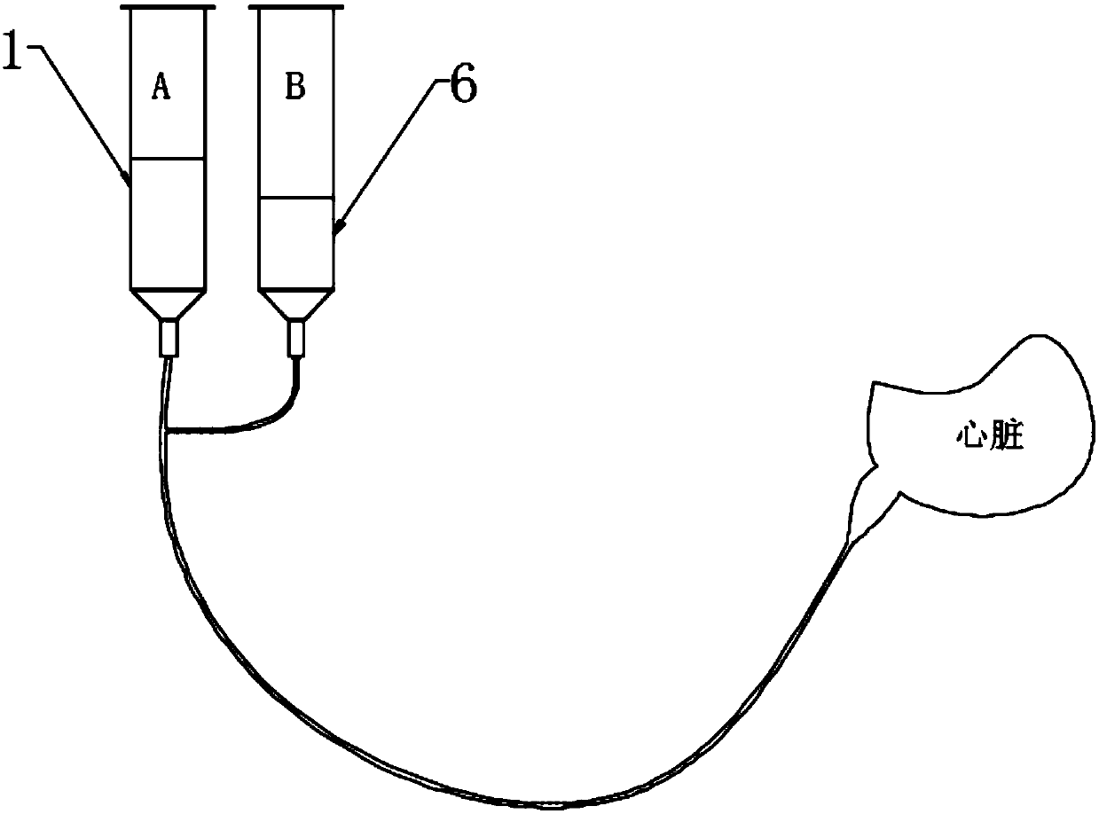
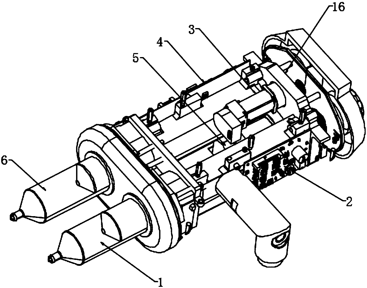
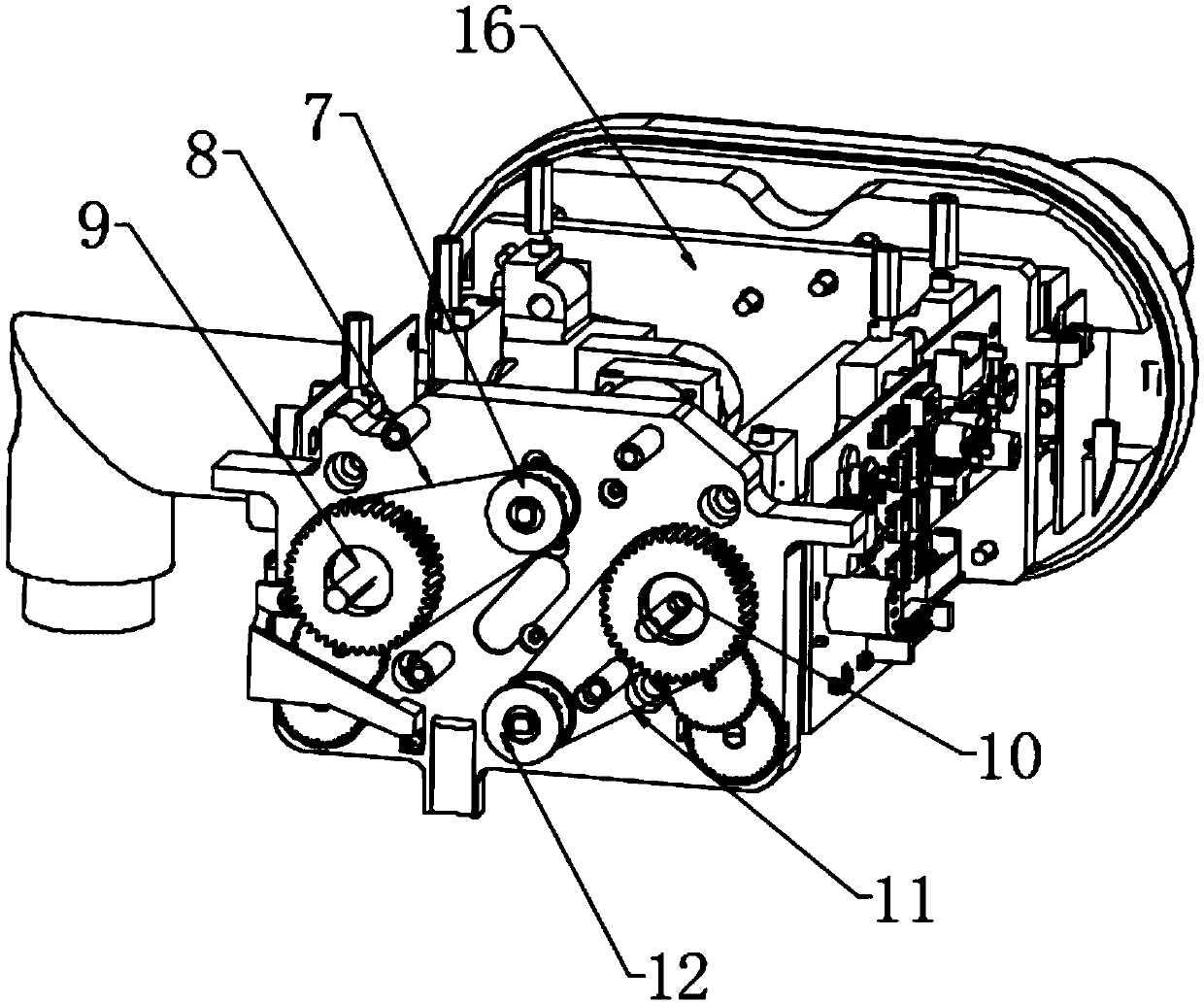
[0025] see Figure 1~4 , in an embodiment of the present invention, a high-pressure injection system for computed tomography angiography, including a first injection syringe 1, a second injection syringe 6 and a first injection syringe 1 and a second injection syringe 6 The mounting frame body 16, the heads of the first injection syringe 1 and the second injection syringe 6 are connected to the heart through the same catheter, and the first injection syringe 1 and the second injection syringe 6 are fixed on the mounting frame body 16, the mounting frame body 16 is equipped with a power assembly that drives the injection of the first injection syringe 1 and the second injection syringe 6, and the power assembly includes the first injection motor 3, the second injection motor 5 and the rotating The first screw nut 9 and the second screw nut 10 arranged at the end of the mounting bracket body 16, the output shaft of the first injection motor 3 and the shaft section of the first s...
Embodiment 2
[0028] see Figure 5 , the embodiment of the present invention differs from Embodiment 1 in that: the high-pressure injection system further includes a control system for controlling the first control drive plate 2 and the second control drive plate 4, and the control system includes a setting unit 17. Determination unit 18 and output control unit 19, the setting unit 17 is used to pre-set the injection steps and injection data; the injection data includes injection volume, injection rate and injection time, and the determination unit 18 uses Determine and execute according to the scheme set by the setting unit 17; the output regulation unit 19 is used to adjust the rotation speed of the first regulation driving plate 2 and the second regulation driving plate 4 and The direction of rotation is regulated; the change of the rotation rate of the first regulation driving plate 2 and the second regulation driving plate 4 can make the speed of contrast agent and saline injection cha...
PUM
 Abstract
Description
Claims
Application Information
 - R&D Engineer
- R&D Manager
- IP Professional
- Industry Leading Data Capabilities
- Powerful AI technology
- Patent DNA Extraction
Browse by: Latest US Patents, China's latest patents, Technical Efficacy Thesaurus, Application Domain, Technology Topic, Popular Technical Reports.
© 2024 PatSnap. All rights reserved.Legal|Privacy policy|Modern Slavery Act Transparency Statement|Sitemap|About US| Contact US: help@patsnap.com