
A Fast Reactor Core Coolant Flow Distribution Method Based on Pressure Drop Compensation

A technology of flow distribution and pressure drop compensation, which is applied in the direction of reactors, reactor fuel elements, and reduction of greenhouse gases, etc., can solve the problems of reactor economic decline, transitional cooling of peripheral components, etc., and achieve uniform overall flow distribution, uniform distribution, and effective cooling uniform effect

Active Publication Date: 2020-05-19
CHINA INSTITUTE OF ATOMIC ENERGY
View PDF3 Cites 0 Cited by
  • Summary
  • Abstract
  • Description
  • Claims
  • Application Information

AI Technical Summary

Problems solved by technology

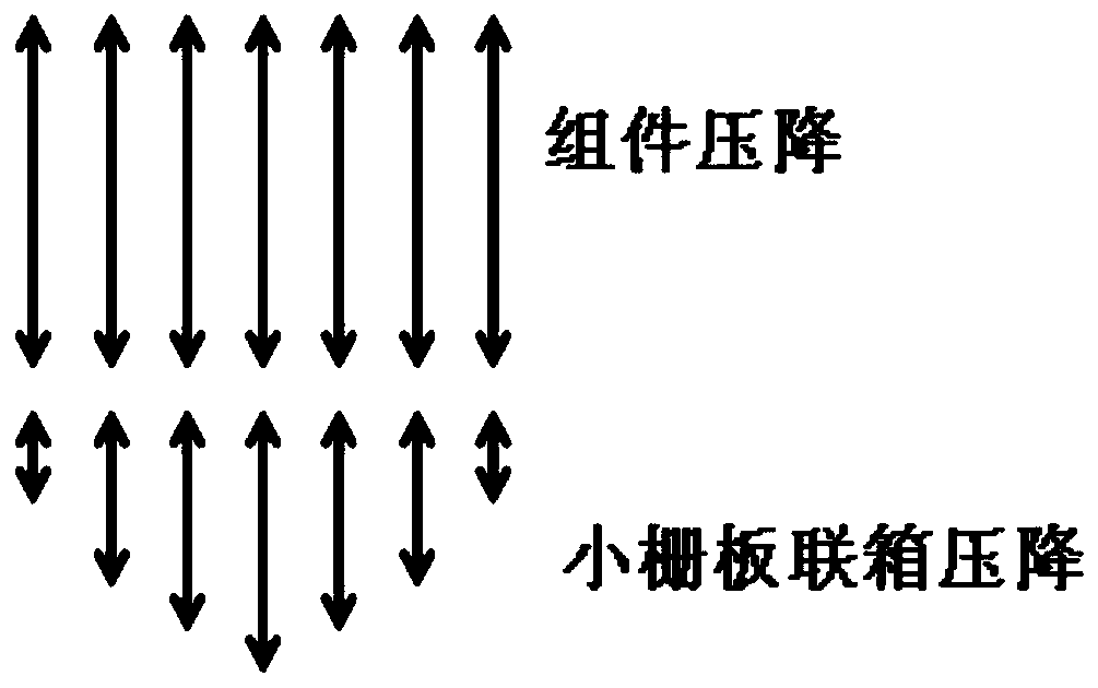
In this case, in order to ensure the equal pressure surface at the outlet of the main pipe and the outlet of the core, the flow actually distributed to the peripheral components will be larger than the design value Q w Large, resulting in excessive cooling of peripheral components, resulting in a decline in the economics of the reactor

Method used


Image

  • A Fast Reactor Core Coolant Flow Distribution Method Based on Pressure Drop Compensation
  • A Fast Reactor Core Coolant Flow Distribution Method Based on Pressure Drop Compensation
  • A Fast Reactor Core Coolant Flow Distribution Method Based on Pressure Drop Compensation

Examples


Embodiment Construction

[0031] The present application will be further elaborated below in conjunction with the accompanying drawings and specific implementation methods.

[0032] A fast reactor core coolant flow distribution method based on pressure drop compensation, the method comprising the following steps:

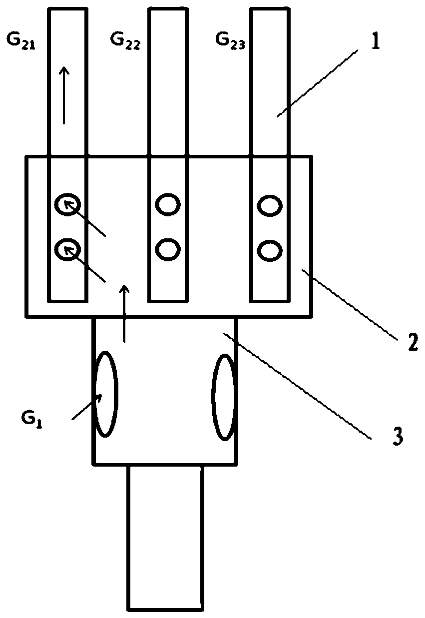
[0033] (1) Count the number of small grille headers, and number them sequentially from 1 to K from the middle to the periphery;

[0034] Since there are 7 components on each small grid header, the components on each small grid header are recorded as K-1~K-7;

[0035] (2) Draw the relationship curve between the core assembly in the outer fuel zone and the minimum coolant flow rate

[0036] Calculate the minimum coolant flow required by the component according to the power of each component; use the component number as the abscissa and the minimum coolant flow as the ordinate to draw the minimum coolant flow curve of the core component and the minimum coolant flow, respectively Obtain the mi...


PUM


Abstract

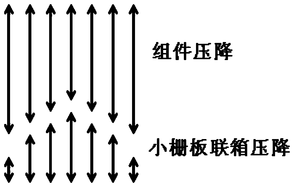
The invention belongs to the technical field of sodium-cooled fast reactors and discloses a method for distributing the flow of a fast reactor core cooling agent based on pressure drop compensation. According to the method, the flow is distributed by uniformizing the pressure drop of the cooling agent flowing through each assembly and the sum of the pressure drops of small grid tray headers through pressure drop compensation. The method has the beneficial effects that a certain cooling effect can be guaranteed, and the operation cost of a reactor can be lowered.

Description

technical field [0001] The invention belongs to the technical field of sodium-cooled fast reactors, in particular to a fast reactor core coolant flow distribution method based on pressure drop compensation. Background technique [0002] In the BN series (the BN series is a sodium-cooled fast reactor developed by China and Russia) fast neutron reactors, the thermal hydraulic structure design adopts a unique structural form of large grid header-small grid header-component. Among them, the power of the components in the middle area is high, and the flow to be distributed is large; the power of the components in the periphery is small, and the flow to be distributed is small. The small grid headers are also arranged from the middle to the periphery, and one small grid corresponds to seven components, so the flow rate of the small grid headers is also large in the middle and small in the peripheral positions. [0003] During core thermal-hydraulic design, the pressure drop ΔP of...

Claims


Application Information

Patent Timeline
Patent Type & Authority Patents(China)
IPC IPC(8): G21C19/04
CPCG21C19/04Y02E30/30
Inventor 李淞周志伟冯预恒林超刘光耀马晓薛秀丽
Owner CHINA INSTITUTE OF ATOMIC ENERGY
Learn More