
Radar signal recognition method based on quantum particle swarm convolutional neural network

A convolutional neural network and quantum particle swarm technology, applied to radio wave measurement systems, instruments, etc., can solve problems such as unsatisfactory recognition accuracy, unguaranteed generalization ability, and complex calculation models, and achieve effective optimization results. Reduce the time of feature extraction and identify the effect of accurate model

Active Publication Date: 2019-04-09
JIANGSU UNIV OF SCI & TECH
View PDF6 Cites 24 Cited by
  • Summary
  • Abstract
  • Description
  • Claims
  • Application Information

AI Technical Summary

Problems solved by technology

However, the above methods cannot completely solve the changing, complex and dense environmental problems and signal waveform problems faced by the current radar signal recognition field.
The above method consumes a lot of time on the feature extraction of the signal, and the effect of feature extraction is often not good, and the extracted features are not representative. In the case of low signal-to-noise ratio, the recognition accuracy of the above method is even less ideal. up
The disadvantages of traditional identification methods Artificial neural network (Neural Network, NN) technology can be well avoided, but the core reverse calculation training algorithm of traditional neural network often adopts error backpropagation (Backpropagation algorithm, BP) algorithm, BP algorithm It is easy to make the network fall into local optimum, and the convergence speed is slow, the generalization ability cannot be guaranteed, and the calculation model is also relatively complicated

Method used


Image

  • Radar signal recognition method based on quantum particle swarm convolutional neural network
  • Radar signal recognition method based on quantum particle swarm convolutional neural network
  • Radar signal recognition method based on quantum particle swarm convolutional neural network

Examples


Embodiment Construction

[0040] The technical solution of the present invention will be further described below in conjunction with the accompanying drawings.

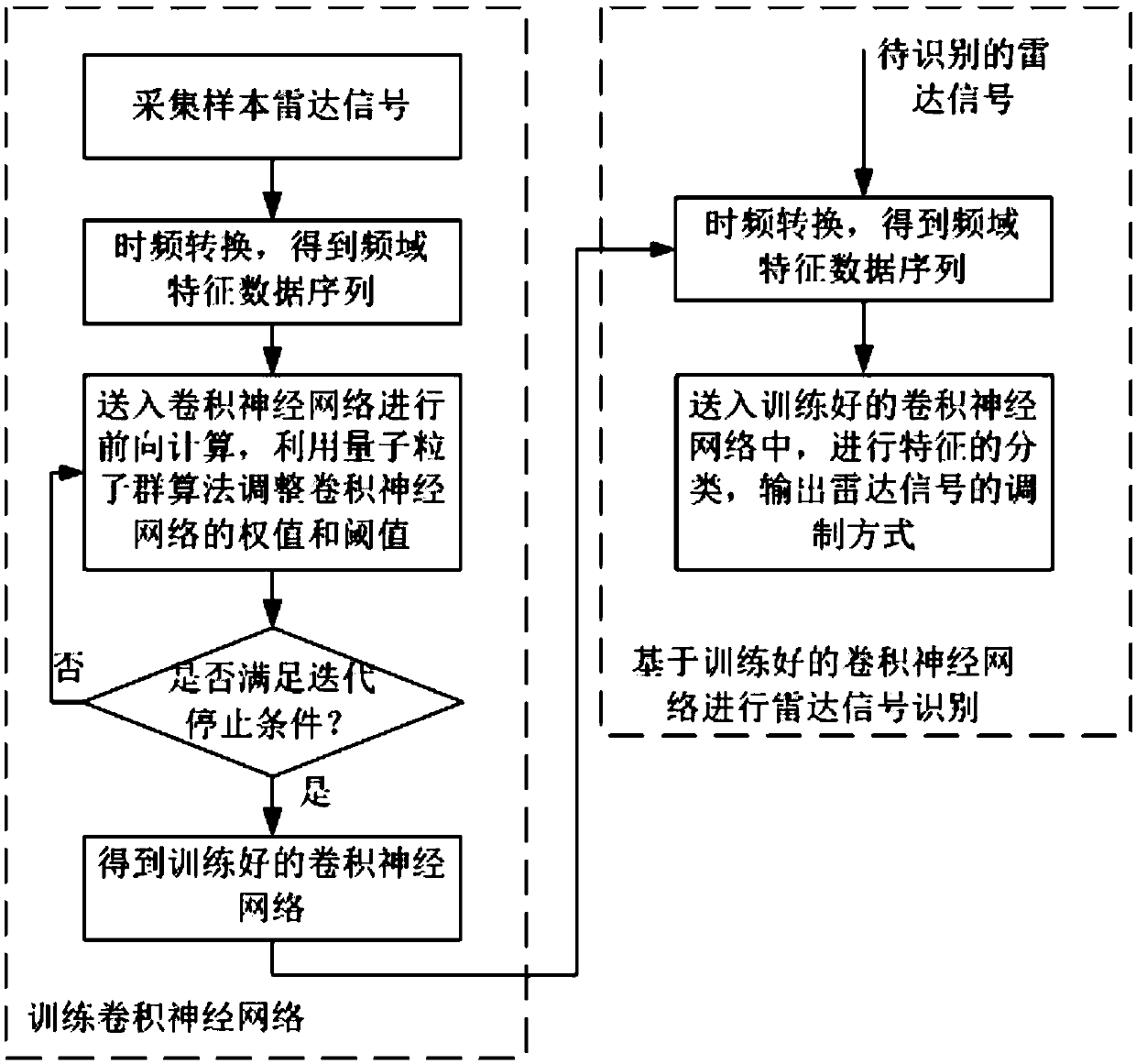
[0041] figure 1Shows the flowchart of the radar signal recognition method based on the quantum particle swarm convolutional neural network according to the present invention, as shown in the figure, the method mainly includes two stages: training the convolutional neural network and utilizing the trained convolutional neural network Recognize radar signals. The process of training convolutional neural network includes: collecting radar signals with different modulation modes, transforming time domain data into frequency domain data, and obtaining frequency domain feature data sequences as training samples; sending training samples into Forward calculation is performed in the convolutional neural network, and the quantum particle swarm algorithm is used to adjust the weight and threshold of the convolutional neural network. When the preset iter...


PUM


Abstract

The invention discloses a radar signal recognition method based on a quantum particle swarm convolutional neural network. The method comprises the following steps: 1) training a convolutional neural network, namely acquiring a radar signal containing different modulation ways, converting time domain data into frequency domain data, obtaining a frequency domain characteristic data sequence, and taking the frequency domain characteristic data sequence as a training sample; sending the training sample into the convolutional neural network, performing forward calculation, and adjusting a weight and a threshold of the convolutional neural network by using a quantum particle swarm algorithm, so that a well trained convolutional neural network is obtained; and 2) based on the well trained convolutional neural network, performing radar signal recognition, namely performing time-frequency conversion on an acquired to-be-recognized radar signal; and sending the obtained frequency domain data into the well trained convolutional neural network in the step 1), and outputting a modulation way of the radar signal. Simulation experiments prove that the method disclosed by the invention improves accuracy and efficiency of recognition of a radar emitter signal, and good solution is provided for a radar signal emitter recognition problem in an increasingly complex electromagnetic environment.

Description

technical field [0001] The invention relates to a radar signal identification method, in particular to a method for identifying different modulation modes of radar signals based on a quantum particle swarm algorithm and a convolutional neural network. Background technique [0002] Radar signal recognition is a key process in Electronic Intelligence Reconnaissance (ELINT), Electronic Support Reconnaissance (ESM) and Radar Threat Warning (RWR) systems, but with the rapid development of modern electronic information technology, the electromagnetic environment is becoming increasingly dense and complex. Systematic radars are constantly emerging, and radar signal waveforms are becoming more and more complex. Traditional radar signal identification methods can no longer meet the needs of modern electronic warfare. [0003] In response to the above problems, many experts and scholars have proposed identification methods such as principal component analysis, methods based on support...

Claims


Application Information

Patent Timeline
IPC IPC(8): G01S7/41
CPCG01S7/411G01S7/417Y02T10/40
Inventor 田雨波赵毅范箫鸿夏俊
Owner JIANGSU UNIV OF SCI & TECH
Learn More