
PCBA color acquisition card based on fiber transmission

A color acquisition and PCB board technology, applied in the field of color recognition, can solve the problems of wrong color judgment, low measurement efficiency, large occupied volume, etc., and achieve the effects of preventing accidental detachment, convenient detection, and convenient expansion

Active Publication Date: 2019-04-09
襄阳蓬达高新科技有限公司
View PDF7 Cites 4 Cited by
  • Summary
  • Abstract
  • Description
  • Claims
  • Application Information

AI Technical Summary

Problems solved by technology

[0003] However, the visual method cannot accurately identify subtle color differences, and color judgment errors often occur. The color difference between two color sources, but the tristimulus value and chromaticity coordinates of the color source cannot be accurately measured. When taking photos with industrial cameras, according to different algorithms, most color recognition can be achieved, but industrial cameras are expensive because of the focal length. The reason is that when the volume of the product is large, it is necessary to make a larger dark room to filter out the ambient light, and to fill in the light for non-luminous objects. The reflected light will also affect the collection while the light is filled. The color sensor has high accuracy in identifying colors and is small in size. , is an ideal color acquisition solution, but the disadvantage is that mature products are inconvenient when applied to non-standard equipment, occupy a large volume when arraying, and the cost will rise linearly. Therefore, we propose a A PCBA color acquisition card based on optical fiber transmission

Method used


Image

  • PCBA color acquisition card based on fiber transmission
  • PCBA color acquisition card based on fiber transmission
  • PCBA color acquisition card based on fiber transmission

Examples


Embodiment Construction

[0022] The following will clearly and completely describe the technical solutions in the embodiments of the present invention with reference to the accompanying drawings in the embodiments of the present invention. Obviously, the described embodiments are only some of the embodiments of the present invention, not all of them. Based on the embodiments of the present invention, all other embodiments obtained by persons of ordinary skill in the art without making creative efforts belong to the protection scope of the present invention.

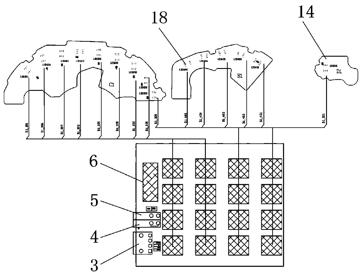
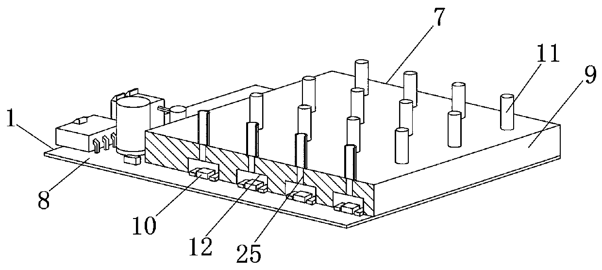
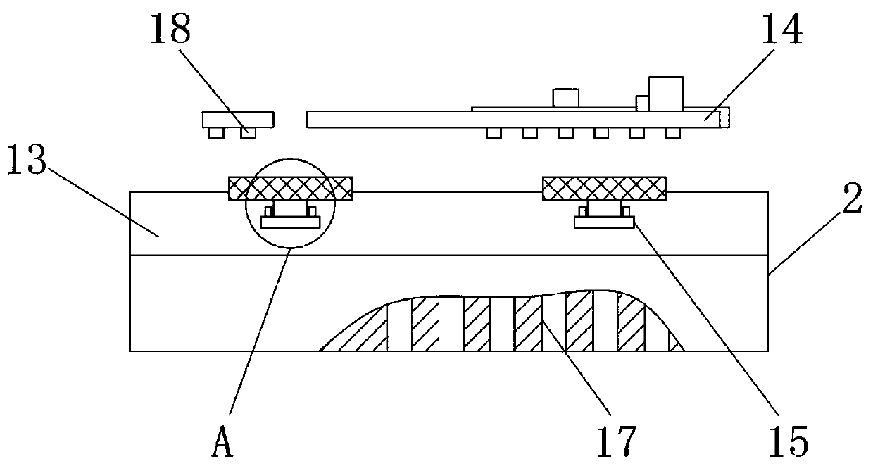
[0023] see Figure 1-5 , the present invention provides a technical solution: a PCBA color acquisition card based on optical fiber conduction, comprising a color acquisition board 1 and a product fixing station 2, the color acquisition board 1 is composed of a power interface 3, an RS485 bus interface 4, and an RS485 bus outlet 5. Microcontroller 6, color collection component 7 and PCB board 8 are composed, and described power interface 3, RS485 ...


PUM


Abstract

The invention discloses a PCBA color acquisition card based on fiber transmission. The PCBA color acquisition card comprises: a color acquisition board and a product fixing table. The color acquisition board is comprised of a power interface, an RS bus interface, an RS bus outlet, a microcontroller, a color acquisition component, and a PCB board. The power interface, the RS bus interface, the RS bus outlet and the microcontroller are all mounted and fixed on one end of the PCB board. The color acquisition component is mounted on the PCB board away from the end of the power interface. The microcontroller is electrically connected to the power interface, the RS bus interface, and the RS bus outlet. The color acquisition board of the invention integrates a fiber fixing board, and can be externally connected with the fiber, so that the color of the product can be acquired collectively. Because the color is transmitted by the fiber, the color can be acquired in a fixed manner regardless ofwhether the product LED lights are on the front or the back. There is no need to increase product movement and rotation function, which makes the detection of product color more convenient. The coloracquisition board adopts RS485 communication, which can work simultaneously in multiple machines. When the product LED lights are too much, the invention can be easily extended.

Description

technical field [0001] The invention relates to the technical field of color recognition, in particular to a PCBA color acquisition card based on optical fiber transmission. Background technique [0002] There are many methods of color recognition, such as visual method, photoelectric integration method, camera image processing and color sensor. [0003] However, the visual method cannot accurately identify subtle color differences, and color judgment errors often occur. The color difference between two color sources, but the tristimulus value and chromaticity coordinates of the color source cannot be accurately measured. When taking photos with industrial cameras, according to different algorithms, most color recognition can be achieved, but industrial cameras are expensive because of the focal length. The reason is that when the volume of the product is large, it is necessary to make a larger dark room to filter out the ambient light, and to fill in the light for non-lumi...

Claims


Application Information

Patent Timeline
IPC IPC(8): G01J3/46G01J3/02
CPCG01J3/0202G01J3/46
Inventor 耿春红易传伟王明杨开鹏王飞
Owner 襄阳蓬达高新科技有限公司
Learn More