
Wing movement airfoil

A motion and airfoil technology, applied in the field of wing motion airfoil, can solve problems such as affecting aerodynamic shape, reducing fatigue life, increasing weight, etc., achieving the effect of simple driving form, accurate deformation and easy control, and reducing structural weight.

Inactive Publication Date: 2019-04-09
XIAN AIRCRAFT DESIGN INST OF AVIATION IND OF CHINA
View PDF0 Cites 6 Cited by
  • Summary
  • Abstract
  • Description
  • Claims
  • Application Information

AI Technical Summary

Problems solved by technology

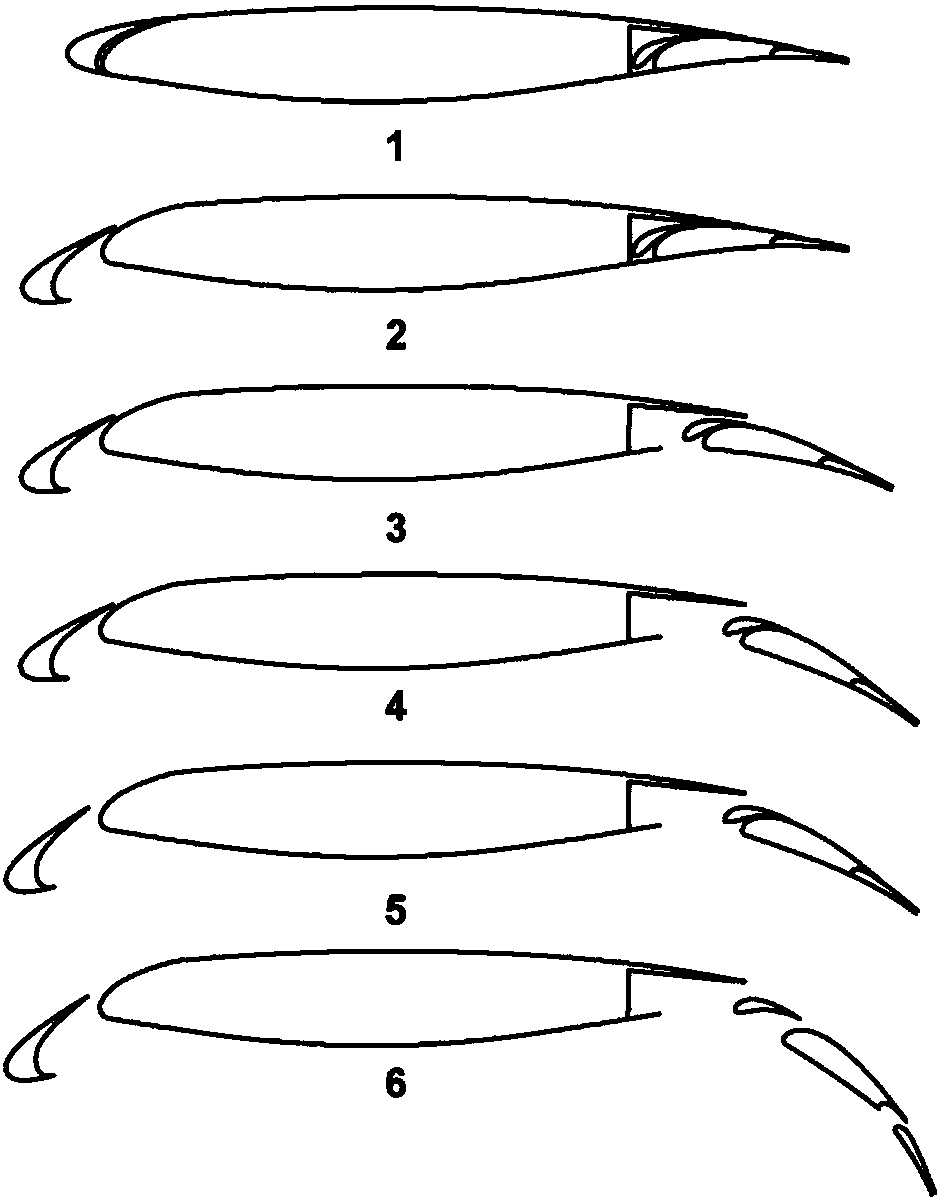
These structural gaps will affect the aerodynamic shape of the wing. While increasing the resistance, the fatigue life of the surrounding structure of the gap will be greatly reduced due to the influence of airflow. The structural form is shown in figure 1
At the same time, these kinematic mechanisms need to be equipped with special fairings on the airfoil, which increases the weight and seriously affects the aerodynamic shape

Method used


Image

  • Wing movement airfoil
  • Wing movement airfoil

Examples


Embodiment Construction

[0011] In order to make the objectives, technical solutions and advantages of the present invention clearer, the technical solutions in the embodiments of the present invention will be described in more detail below in conjunction with the drawings in the embodiments of the present invention. In the drawings, the same or similar reference numerals denote the same or similar elements or elements having the same or similar functions throughout. The described embodiments are some, but not all, embodiments of the invention. The embodiments described below by referring to the figures are exemplary and are intended to explain the present invention and should not be construed as limiting the present invention. Based on the embodiments of the present invention, all other embodiments obtained by persons of ordinary skill in the art without creative efforts fall within the protection scope of the present invention.

[0012] The wing motion airfoil of the present invention will be descr...


PUM


Abstract

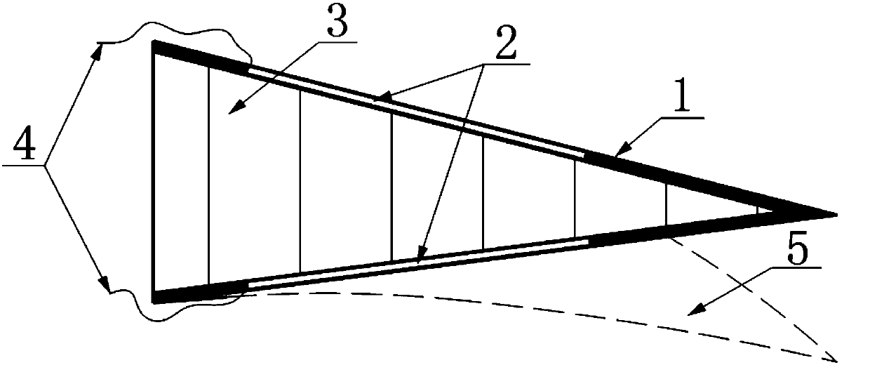
The invention provides a wing movement airfoil which comprises an elastic skin (1), shape memory alloy wires (2) and a metal honeycomb (3), the elastic skin (1) is laid on the surface of the wing movement airfoil to adapt to tangential deformation, the shape memory alloy wires (2) are implanted into the elastic skin (1), and the interior of the wing movement airfoil is filled with the metal honeycomb (3) to provide normal support. Different voltages are applied to the shape memory alloy wires (2) in the upper elastic skin (1) and the lower elastic skin (1) of the wing movement airfoil, so thatthe shape memory alloy wires (2) generate phase change, and smooth deflection of the wing movement airfoil is achieved. According to the wing moving airfoil provided by the invention, the airfoil cankeep the structure smooth, continuous and gapless in the moving process. Electric signals are used for driving deformation, and deformation is more accurate and easier to control. The driving mode issimple, a fairing does not need to be additionally arranged on the airfoil, and the structural weight can be effectively reduced.

Description

technical field [0001] The invention belongs to the field of aircraft structure design, and in particular relates to a wing moving airfoil. Background technique [0002] The moving surface of the wing changes the wing area of ​​the aircraft by changing the shape of the wing surface. The traditional trailing edge of the wing adopts structures such as slide rails and screws, which will generate structural gaps on the upper and lower surfaces of the wing while moving. These structural gaps will affect the aerodynamic shape of the wing. While increasing the resistance, the fatigue life of the surrounding structure of the gap will be greatly reduced due to the influence of airflow. The structural form is shown in figure 1 . At the same time, these kinematic mechanisms need to be provided with special fairings on the airfoil, which increases the weight and seriously affects the aerodynamic shape. Contents of the invention [0003] The object of the present invention is to pro...

Claims


Application Information

Patent Timeline
Patent Type & Authority Applications(China)
IPC IPC(8): B64C3/14B64C3/38
CPCB64C3/14B64C3/38
Inventor 高进吴晓龙郭亚飞徐方舟宋维博
Owner XIAN AIRCRAFT DESIGN INST OF AVIATION IND OF CHINA
Learn More