
A composite manufacturing method of arc additive forming and generative electrolytic machining

A technology of additive forming and generating electrolysis, which is applied in the direction of electric processing equipment, electrochemical processing equipment, manufacturing tools, etc., can solve the problems of low shape consistency, aggravating the non-uniformity of heat source action space, complex forming parts space, and size Limit the difficulty of machining and other problems, achieve the effect of maintaining the consistency of the forming shape, avoiding the coarse solidification texture, and improving the quality of the additive forming

Active Publication Date: 2020-08-07
FUZHOU UNIV
View PDF5 Cites 0 Cited by
  • Summary
  • Abstract
  • Description
  • Claims
  • Application Information

AI Technical Summary

Problems solved by technology

[0005] However, the surface quality of parts manufactured by additive manufacturing is poor, and subsequent machining is generally required to meet the requirements of use. However, complex parts with near-net shape cannot perform multi-process precision machining on blank raw materials like traditional processing technology, and the molten pool is point by point. Solidified complex parts are generally difficult to carry out subsequent precision machining due to shape and size constraints. Therefore, online subtractive precision machining has become a necessary process for arc additive manufacturing of complex parts to meet final service requirements.
However, traditional milling and grinding finishing need to exert force on the processing object, and complex structures such as hollowing out and cantilever bring challenges to traditional machining. Online integration of a flexible low-load or no-load subtractive machining method has become The inevitable trend of additive manufacturing of complex and precise structures
In addition, the arc additive forming process often causes relatively large thermal stress, and the large-scale structural size features further aggravate the spatial non-uniformity of the heat source. The traditional heat input control, welding and rolling and other residual stress control methods have little effect. Maintaining the uniformity of the temperature field of the formed part, maintaining the consistency of the local temperature field of the molten pool, coordinating stress and strain, and obtaining a consistent solidification morphology have become difficult problems in arc additive forming of large-scale components.
[0006] However, arc additive forming is a rapid heating and quenching free deposition forming process without a mold-constrained molten pool. The forming surface quality is poor and the shape consistency is low. Formed parts generally require secondary machining, and complex formed parts are subject to space constraints. , Difficulty in machining due to size limitation

Method used


Image

  • A composite manufacturing method of arc additive forming and generative electrolytic machining

Examples


Embodiment Construction

[0024] In order to make the above-mentioned features and advantages of the present invention more comprehensible, the following specific embodiments are described in detail with reference to the accompanying drawings, but the present invention is not limited thereto.

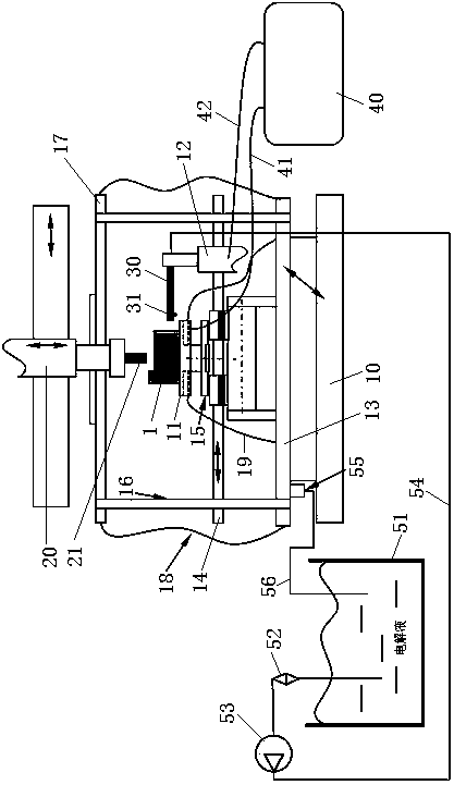
[0025] refer to figure 1

[0026] A compound manufacturing method of electric arc additive forming and generative electrolytic machining, comprising the following steps:

[0027] (1) Path planning is carried out after the part model is layered and sliced, and the path execution file is transmitted to the composite manufacturing equipment system at the same time. The welding torch is placed at the starting point of the forming. After the arc is started, the welding torch takes the path centerline as the trajectory according to the set process parameters , for continuous arc additive manufacturing;

[0028] (2) After the compound manufacturing equipment system is added to form 10mm from bottom to top, turn on th...


PUM

PropertyMeasurementUnit
diameteraaaaaaaaaa

Abstract

The invention relates to an arc additive forming and electrochemical contour evolution machining composite manufacturing method. The arc additive forming and electrochemical contour evolution machining composite manufacturing method comprises the following steps that a part model is sliced in a layered mode, then path planning is performed, and path execution files are transmitted to a composite manufacturing equipment system at the same time; after an additive is formed by 10 mm from bottom to top, an electrolyte is provided for a rotating working electrode; the working electrode is enabled to be away from the surface of a workpiece by 5 mm, a power supply system is turned on, and starting point electrolytic machining is performed; the working electrode takes a point-by-point position away from an outer contour line of a path by 5 mm as a motion track for continuous electrochemical contour evolution machining according to set process parameters; the composite manufacturing equipment system detects the current between the working electrode and the workpiece and compares the current with a set current value, and the current is used as a motion signal of point-by-point continuous electrolytic machining; the composite manufacturing equipment system increases the height of the electrolytic machining working electrode according to layer height of layered slicing in the same direction as additive forming; and the increment of a second Z shaft is equal to that of a first Z shaft, and the additive and subtractive composite manufacturing process is completed. The arc additive forming and electrochemical contour evolution machining composite manufacturing method can be conveniently used for achieving additive manufacturing and on-line precision subtractive machining of complex parts.

Description

technical field [0001] The invention relates to a compound manufacturing method of arc additive forming and generative electrolytic machining, and belongs to the field of high-performance metal material additive and subtractive composite manufacturing. Background technique [0002] Faced with the low-cost and high-reliability requirements of new aircraft, its components are gradually becoming larger and more integrated. The arc additive manufacturing technology uses the arc as the energy-carrying beam and adopts layer-by-layer surfacing welding to manufacture metal solid components. This technology is mainly developed based on welding technologies such as TIG, MIG, and SAW. The formed parts are composed of full-weld metal. The forming environment has no restrictions on the size of the formed part, and the forming rate of titanium alloy can reach 4kg / h, so it has incomparable advantages in cost, efficiency and formed part size compared with other additive manufacturing method...

Claims


Application Information

Patent Timeline
Patent Type & Authority Patents(China)
IPC IPC(8): B23P23/00B23K9/04B23H3/00B23H3/02
CPCB23H3/00B23H3/02B23K9/04B23P23/00
Inventor 耿海滨罗键
Owner FUZHOU UNIV
Learn More