Clamping method of special clamp

A fixture and special technology, applied in the attachment, clamping, positioning device and other directions of the shearing machine, can solve the problems of affecting cutting, hidden dangers, poor clamping effect, etc., to facilitate fixing, improve safety performance, and facilitate flexibility. moving effect

Inactive Publication Date: 2019-04-09
广州川也汽车装备有限公司
View PDF10 Cites 0 Cited by
  • Summary
  • Abstract
  • Description
  • Claims
  • Application Information

AI Technical Summary

Problems solved by technology

[0004] The existing steel pipe is long, the clamping effect is not good, and the long-term clamping position of the steel pipe on the fixture is easy to deform. Once the deformation occurs, the steel pipe will become loose and affect the cutting and other operations. At the same time, there are certain safety hazards

Method used


Image

  • Clamping method of special clamp
  • Clamping method of special clamp
  • Clamping method of special clamp

Examples


Embodiment 1

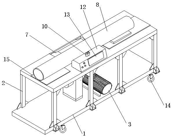
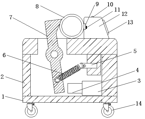
[0044] see figure 1 and figure 2 , a special fixture, including a fixture base 1 with a fixture bracket 2 installed on the upper end, a clamping cylinder 3 connected to the side end of the fixture bracket 2, a piston rod 4 connected to the power output end of the clamping cylinder 3, and a piston rod 4 connected to the inner end of the fixture bracket 2 There is a fixed block 5, the inside of the fixture bracket 2 is provided with a movable pressure plate 7, the middle part of the movable pressure plate 7 is rotatably connected with a rotating shaft, the end of the rotating shaft is fixedly connected with the inner end of the fixture bracket 2, the upper end of the movable pressure plate 7 extends to the upper side of the fixture bracket 2, and the movable pressure plate A tension spring 6 is connected between the lower end of the 7 and the end of the fixed block 5, a fixed pressing block 12 is connected to the upper end of the clamp bracket 2, a steel pipe 8 is arranged betw...

Embodiment 2

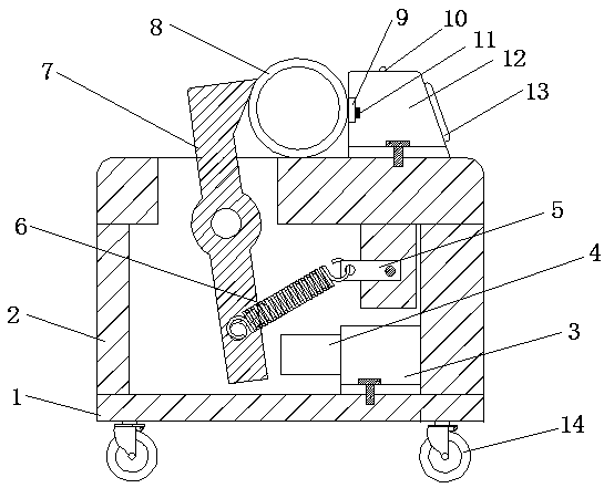
[0059] see image 3 , a special fixture, including a fixture base 1 with a fixture bracket 2 installed on the upper end, a clamping cylinder 3 installed on the side end of the fixture bracket 2 through screws, and a piston rod 4 connected to the power output end of the clamping cylinder 3, inside the fixture bracket 2 The fixed block 5 is installed on the end by screws, and the inside of the fixture bracket 2 is provided with a movable pressure plate 7, and the middle part of the movable pressure plate 7 is rotatably connected with a rotating shaft. On the upper side, a tension spring 6 is connected between the lower end of the movable pressing plate 7 and the end of the fixed block 5, and a fixed pressing block 12 is installed on the upper end of the fixture bracket 2 through screws, and a steel pipe 8 is arranged between the fixed pressing block 12 and the movable pressing plate 7, and fixed The main controller is connected to the briquetting block 12, and the side of the fi...


PUM


Abstract

The invention discloses a clamping method of a special clamp, and belongs to the technical field of clamping. The special clamp comprises a clamp base provided with a clamp support at the upper end, and the side end of the clamp support is connected with a clamping oil cylinder, a fixed block is connected to the inner end of the clamp support, a movable pressing plate is arranged on the inner sideof the clamp support, a rotating shaft is rotationally connected to the middle of the movable pressing plate, and the end part of the rotating shaft is fixedly connected with the inner end of the clamp support, and a stretching spring is connected between the lower end of the movable pressing plate and the tail end of the fixed block, a fixed pressing block is connected to the upper end of the clamp support, and a steel pipe is arranged between the fixed pressing block and the movable pressing plate, the fixed pressing block is connected to a main controller, a pressure detecting mechanism isarranged on one side, close to the steel pipe, of the fixed pressing block, and the steel pipe is stably clamped through a clamp type clamping method, the pressure of the clamping part on the clamp can be detected in real time, and once the pressure exceeds the manual preset threshold value, automatic alarm can realize to remind a worker, the fault information can be transmitted remotely, and thesafety performance is improved to a great extent.

Description

technical field [0001] The invention relates to the field of clamping technology, more specifically, to a clamping method of a special clamp. Background technique [0002] Steel pipe is a hollow long strip of round steel, which is widely used in petroleum, chemical, medical, food, light industry, mechanical instrumentation and other industrial pipelines and mechanical structural components. In addition, when the bending and torsional strength are the same, the weight is lighter, so it is also widely used in the manufacture of mechanical parts and engineering structures. Steel pipes are generally long in length, and sometimes it is necessary to cut a section for other purposes. The general method is to fix the steel pipe first, and then use a cutting machine to cut the required length. However, the steel pipe is easy to roll, and special fixtures are needed to adjust it. It is clamped and fixed. [0003] At present, the improvement speed of fixtures and clamping mechanisms ...

Claims


Application Information

Patent Timeline
Patent Type & Authority Applications(China)
IPC IPC(8): B23D21/00B23D33/02B23Q3/08
CPCB23D21/00B23D33/02B23Q3/082
Inventor 李良金刘晓燕莫桥焕叶俊涛
Owner 广州川也汽车装备有限公司
Why Eureka
Try Eureka