
Silicon-controlled dimming LED (Light Emitting Diode) driving method and circuit

A technology of LED driving and silicon dimming, which is applied in the field of thyristor dimming LED driving circuits, can solve problems such as flickering, and achieve the effect of improving efficiency

Pending Publication Date: 2019-04-05
SHAANXI REACTOR MICROELECTRONICS
View PDF10 Cites 1 Cited by
  • Summary
  • Abstract
  • Description
  • Claims
  • Application Information

AI Technical Summary

Problems solved by technology

[0004] The main purpose of the present invention is to provide a thyristor dimming LED drive circuit, aiming to solve the problem of flicker in the prior art

Method used


Image

  • Silicon-controlled dimming LED (Light Emitting Diode) driving method and circuit
  • Silicon-controlled dimming LED (Light Emitting Diode) driving method and circuit
  • Silicon-controlled dimming LED (Light Emitting Diode) driving method and circuit

Examples


Embodiment Construction

[0030] Below will combine the appended in the embodiment of the present invention figure 1 to attach Figure 6 , clearly and completely describe the technical solutions in the embodiments of the present invention, obviously, the described embodiments are only some embodiments of the present invention, not all embodiments. Based on the embodiments of the present invention, all other embodiments obtained by persons of ordinary skill in the art without making creative efforts belong to the protection scope of the present invention.

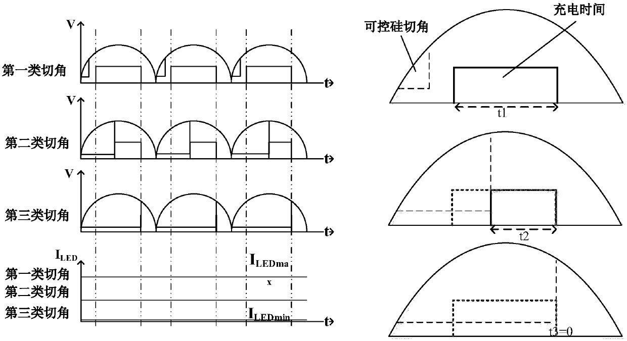
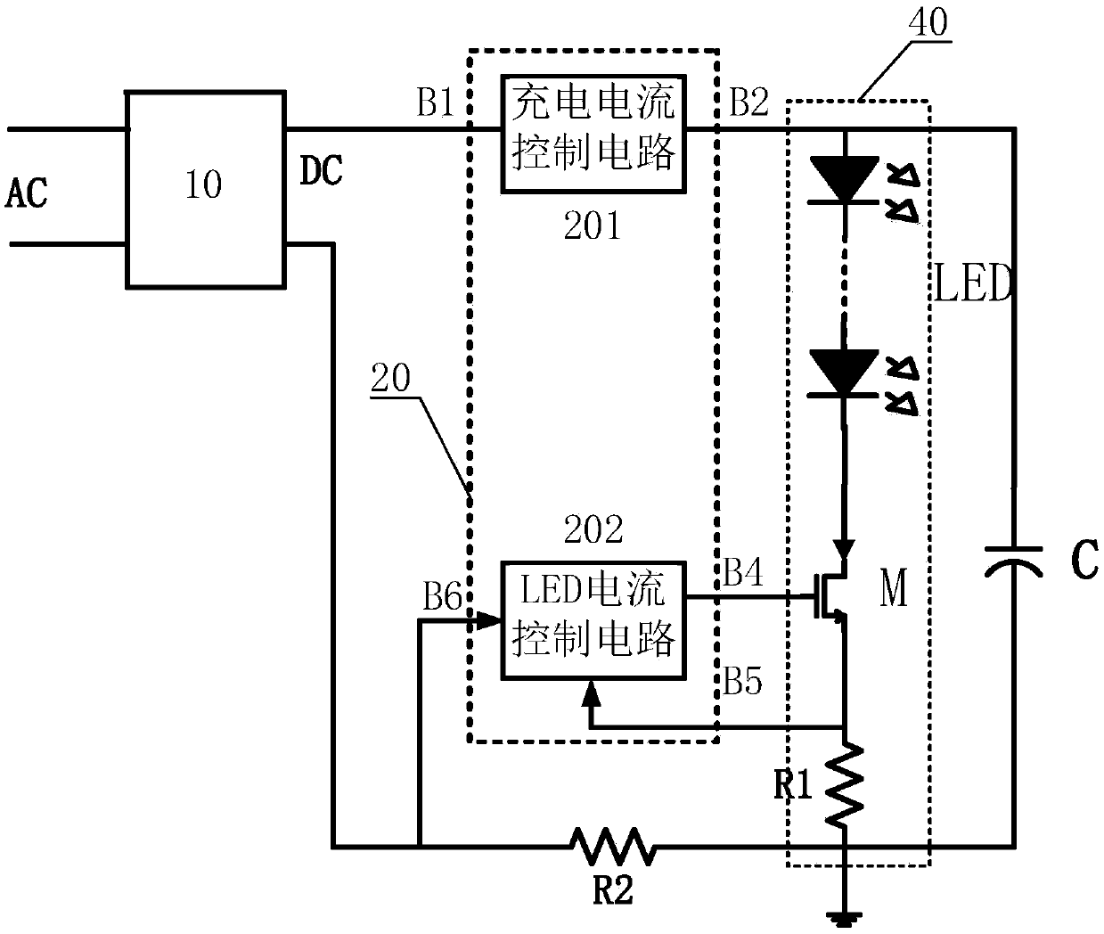
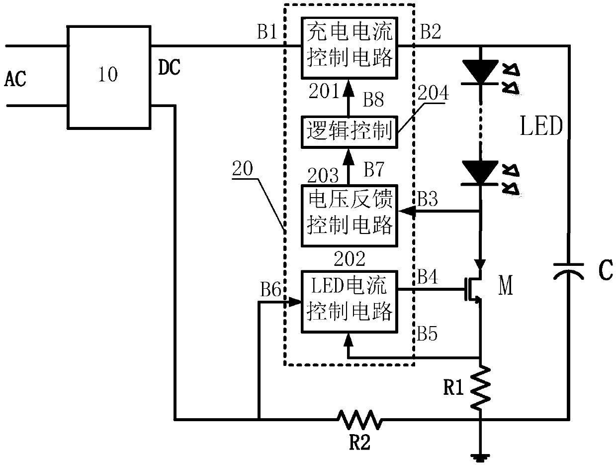
[0031] An embodiment of the present invention provides a thyristor dimming LED drive circuit, which acquires the charging time of a capacitor, and regulates the conduction current of the LED light string according to the charging time.

[0032] More specifically, the regulation of the above conduction current is carried out according to the set rules within the preset range. The longer the charging time is, the larger the current flowing through the...


PUM


Abstract

The invention provides a silicon-controlled dimming LED (Light Emitting Diode) driving method and circuit. The method comprises the steps of acquiring charging time of an energy-storage charging capacitor; and regulating and controlling a break-over current of an LED lamp string according to the charging time. With the silicon-controlled dimming LED driving method and circuit, the stroboflash in silicon-controlled dimming can be eliminated and the market requirements for LED illumination can be satisfied.

Description

technical field [0001] The invention relates to the field of electronic circuits, in particular to a thyristor dimming LED driving circuit. Background technique [0002] Intelligent dimming of LED lighting products is the development trend of the future market. Thyristor dimming is a commonly used technical means. By adjusting the chopping phase of the thyristor dimmer to change the conduction angle, dimming is realized. However, during the dimming process, with the increase of the cutting angle of the thyristor, that is, the decrease of the conduction angle, the charging time of the capacitor is getting shorter and shorter, and the discharging time is getting longer and longer, which will make the average charging current of the capacitor smaller than the discharging current. , eventually lead to capacitor energy storage can not meet the continuous flow of LED within a cycle, resulting in flicker; at the same time, in the process of capacitor discharge, it is often unable t...

Claims


Application Information

Patent Timeline
Patent Type & Authority Applications(China)
IPC IPC(8): H05B33/08H05B44/00
CPCH05B45/00
Inventor 杨世红王虎
Owner SHAANXI REACTOR MICROELECTRONICS
Learn More