Eureka AIR delivers breakthrough ideas for toughest innovation challenges, trusted by R&D personnel around the world.

A High Power Factor Multi-channel Low Ripple Constant Current Output Switching Converter

A switching converter, high power factor technology, applied in the direction of converting DC power input to DC power output, output power conversion device, high-efficiency power electronic conversion, etc. The effect of high flow accuracy, simple control and low cost

Active Publication Date: 2019-07-26
SICHUAN UNIV
View PDF9 Cites 0 Cited by
  • Summary
  • Abstract
  • Description
  • Claims
  • Application Information

AI Technical Summary

Problems solved by technology

[0011] This solution uses a single-stage PFC converter and capacitor charge-discharge balance to achieve high power factor and current sharing control. It has a simple structure and high efficiency, but its output contains a large double power frequency ripple.

Method used


Image

  • A High Power Factor Multi-channel Low Ripple Constant Current Output Switching Converter
  • A High Power Factor Multi-channel Low Ripple Constant Current Output Switching Converter
  • A High Power Factor Multi-channel Low Ripple Constant Current Output Switching Converter

Examples


Embodiment Construction

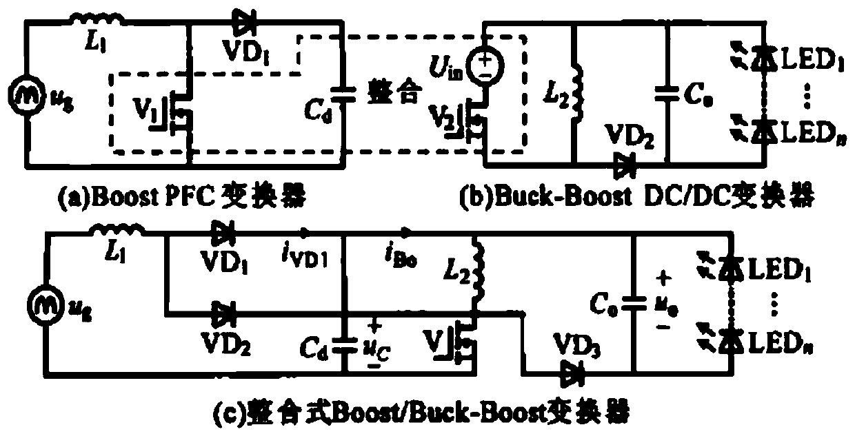
[0041] The present invention will be described in further detail below in conjunction with the accompanying drawings and specific embodiments. Based on the integrated Boost-Buck switching converter, the present invention proposes a brand-new high power factor multi-channel low ripple constant current output switching converter for LED driving. like Figure 8 As shown, the circuit diagram consists of a diode rectifier bridge D b , Input filter inductance L f , Input filter capacitor C f , the main inductance L m , Active switch S 1 , Energy storage capacitor C 2k-2 , Freewheeling diode D 2k-1 , output capacitance C ok and the branch inductance L k , k=1,2,...,n.

[0042] Diode rectifier bridge D b The input terminal of the circuit is connected to the AC power supply, and the upper output terminal is connected to the input filter inductor L in turn. f , the main inductance L m and active switch S 1 D pole; input filter capacitor C f One side is connected to the inp...


PUM


Abstract

The invention discloses a high power factor multi-channel low-ripple constant-current output switch converter, which is used as n-channel LED driving power supply, and the output terminal of the diode rectifier bridge is sequentially connected to the input filter inductor, the main inductor and the D pole of the active switch; the input One side of the filter capacitor is connected between the input filter inductor and the main inductor, and the other side is connected to the lower output end of the diode rectifier bridge; the G pole of the active switch is connected to the control circuit, and the S pole is connected to the lower output end of the diode rectifier bridge; Capacitance in n branch C 2n‑3 The negative plate of the diode is connected D 2n‑2 the anode of the diode D 2n‑2 The cathode connection of the storage capacitor C 2n‑2 The positive plate, the energy storage capacitor C 2n‑2 The negative plate of the active switch is connected to the S pole of the active switch; the output capacitor C on Parallel to LED Sn both ends of the LED Sn The anode of the capacitor is connected to the storage capacitor C 2n‑2 the positive plate of the LED Sn The cathode in turn passes through the branch inductance L n , freewheeling diode D 2n‑1 Connect to the D pole of the active switch. The invention can realize high power factor, low output ripple current and accurate multi-channel current-sharing output control.

Description

technical field [0001] The invention relates to the technical field of LED current sharing, in particular to a high power factor multi-channel low ripple constant current output switching converter. Background technique [0002] With the development of consumer electronics and light-emitting diode (LED) lighting, switching converters with multiple constant current outputs have been widely used in LED driving lighting systems in recent years. The quality of the driving circuit will directly affect the efficiency of the entire lighting system and longevity. High-efficiency, long-life, and highly controllable LED drive circuits are more and more required by people. [0003] Most of the current LED lighting systems connect multiple LEDs in series and parallel to achieve the required lighting intensity and power. In order to ensure that each string of LEDs has the same brightness, it is necessary to control the current flowing through each string of LEDs to be consistent. There...

Claims


Application Information

Patent Timeline
Patent Type & Authority Patents(China)
IPC IPC(8): H02M3/156H02M1/42H02M1/14H05B33/08H05B44/00
CPCH02M1/14H02M1/42H02M3/156H05B45/00H05B45/37Y02B70/10
Inventor 刘雪山李学文周群张哲丰姚昊天杨航李卓城
Owner SICHUAN UNIV
Why Eureka
Eureka Blog
Learn More