
Power parallel current-sharing control circuit

A flow control and circuit technology, applied in the direction of parallel operation of DC power supplies, can solve problems such as difficult work, low reliability, and many restrictions

Pending Publication Date: 2019-05-14
LUOYANG LONGSHENG SCI & TECH
View PDF0 Cites 0 Cited by
  • Summary
  • Abstract
  • Description
  • Claims
  • Application Information

AI Technical Summary

Problems solved by technology

However, through practical applications, it is found that different power supplies are difficult to work in harmony, have many restrictions, and have low reliability.

Method used


Image

  • Power parallel current-sharing control circuit

Examples


Embodiment Construction

[0014] The technical solution of the present invention will be described in further detail below in conjunction with the accompanying drawings and embodiments.

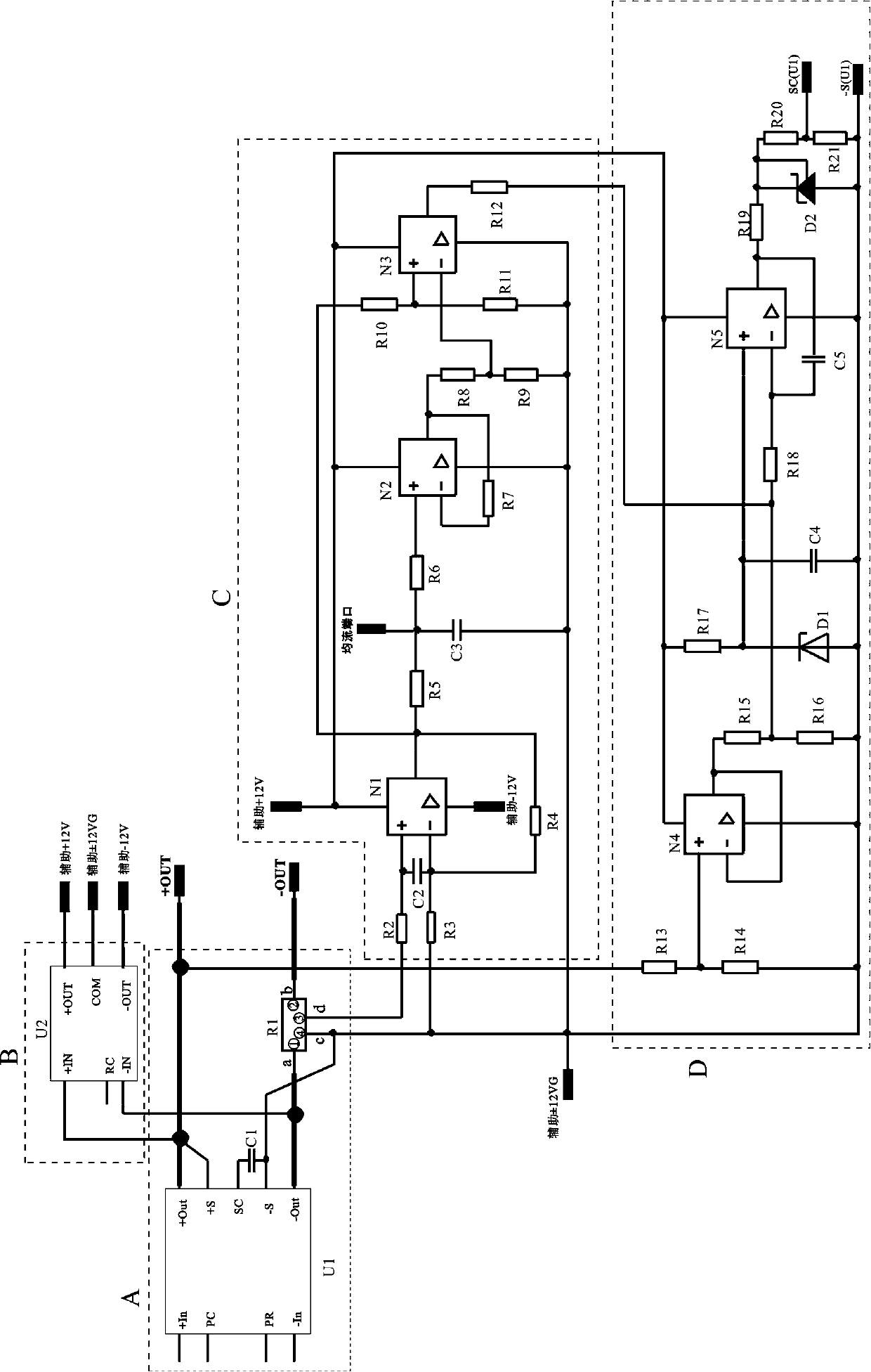
[0015] like figure 1 As shown, the power supply is connected in parallel with the current sharing control circuit, which includes a sampling circuit A, an auxiliary source circuit B, a current sharing circuit C, and a voltage stabilizing circuit D. The sampling circuit A includes a first DC / DC module U1, a first DC / DC module The positive output terminal (+Out pin) of the DC module U1 is connected to the sampling positive terminal (+S pin) and connected to the positive output terminal (+OUT) of the current sharing control circuit, and the voltage regulation terminal (SC pin) is connected to the sampling negative terminal. The first slow start capacitor C1 is connected between the terminals (-S pin), and the negative output terminal (-Out pin) is connected to the negative output terminal (-OUT) of the current sharing co...


PUM


Abstract

The invention discloses a power parallel current-sharing control circuit. The power parallel current-sharing control circuit comprises a sampling circuit, an auxiliary source circuit, a current-sharing circuit and a voltage-stabilizing circuit, wherein a positive output end and a negative output end of the sampling circuit are connected with a positive output end and a negative output end of the current-sharing control circuit respectively, the positive output end and the negative output end of the sampling circuit are connected with the auxiliary source circuit, a first auxiliary source, a second auxiliary source and a third auxiliary source in the auxiliary source circuit supply power to the current-sharing circuit, and the current-sharing circuit is connected with the voltage-stabilizing circuit. According to the power parallel current-sharing control circuit, a boundary control method is adopted, an average current is introduced, current feedback is utilized to control DC / DC moduleoutput voltage, automatic regulation of the DC / DC module output voltage is realized, and the purpose that output currents of all power sources are balanced is achieved.

Description

technical field [0001] The invention relates to the technical field of power electronics, in particular to a power supply parallel current sharing control circuit, which is suitable for a power supply multi-channel output parallel current sharing control system. Background technique [0002] The parallel connection of power supplies can expand the output power of the system, and multiple power supplies can be connected in parallel to form a redundant power supply system, which can improve the reliability of the system. In recent years, the market demand for parallel current sharing of power supplies has increased, and higher requirements have been put forward for the accuracy of parallel current sharing. [0003] At present, the solution to achieve power supply current sharing is through the parallel bus PR pin of the DC / DC module. This pin is a bidirectional interface that can send or receive information between modules. Its pulse signal can make each DC / DC The high-freque...

Claims


Application Information

Patent Timeline
Patent Type & Authority Applications(China)
IPC IPC(8): H02J1/10
Inventor 胡锦毅张峥许峰姜蜜
Owner LUOYANG LONGSHENG SCI & TECH
Learn More