
Dual-connection communication structure and uplink method thereof

A communication structure, dual-connection technology, applied in the field of communication, can solve the problems of increasing transmission power, inability to define high-power transmission terminals, and inability to meet

Active Publication Date: 2019-04-05
CHINA UNITED NETWORK COMM GRP CO LTD
View PDF4 Cites 15 Cited by
  • Summary
  • Abstract
  • Description
  • Claims
  • Application Information

AI Technical Summary

Problems solved by technology

However, in order to compensate for the increase in path loss in the high-frequency band or the coverage shrinkage caused by the poor signal at the location of the terminal, in the 2.6GHz, 3.5GHz and 4.9GHz frequency bands, the maximum transmit power of a higher-power terminal is defined, which is increased to 26dBm, in this case, the base station using TDD (Time Division Duplexing, time division duplex) mode, that is, TDD base station, can be realized by adjusting the uplink and downlink duty cycle, and the base station using FDD (Frequency Division Duplexing, frequency division duplex) mode, that is, FDD base station can not meet the SAR limit requirements
Therefore, under the NSA architecture, if one of LTE and NR uses FDD mode to transmit information, and the other uses TDD mode to transmit information, in order to ensure that the terminal transmit power on all frequency bands is 23dBm (total power of LTE+NR), it is High-power transmitting terminals cannot be defined, but under the NSA architecture, it will not be possible to compensate for the weak uplink coverage by increasing the transmitting power

Method used


Image

  • Dual-connection communication structure and uplink method thereof
  • Dual-connection communication structure and uplink method thereof
  • Dual-connection communication structure and uplink method thereof

Examples


Embodiment Construction

[0033] The following will clearly and completely describe the technical solutions in the embodiments of the present invention with reference to the accompanying drawings in the embodiments of the present invention. Obviously, the described embodiments are only some, not all, embodiments of the present invention. Based on the embodiments of the present invention, all other embodiments obtained by persons of ordinary skill in the art without making creative efforts belong to the protection scope of the present invention.

[0034] It should be noted that, in the embodiments of the present invention, words such as "exemplary" or "for example" are used for example, illustration or illustration. Any embodiment or design solution described as "exemplary" or "for example" in the embodiments of the present invention shall not be construed as being more preferred or more advantageous than other embodiments or design solutions. Rather, the use of words such as "exemplary" or "such as" is...


PUM


Abstract

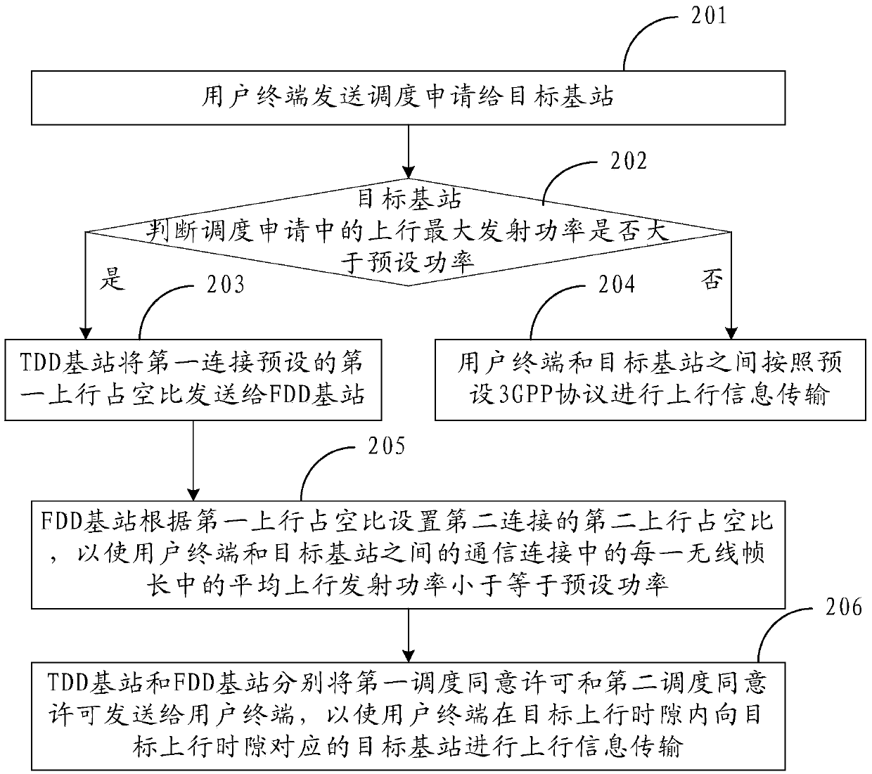
The embodiment of the invention provides a dual-connection communication structure and an uplink method thereof, which relate to the field of communication and can satisfy the SAR (Specific AbsorptionRate) limit requirement while guaranteeing the uplink coverage. The method includes the following steps: a user terminal sends a scheduling request containing the maximum uplink transmission power toa TDD (Time Division Duplexing) base station and an FDD (Frequency Division Duplexing) base station; when the maximum uplink transmission power is determined to be greater than a preset power, the TDD base station sends a first uplink duty cycle to the FDD base station; the FDD base station sets a second uplink duty cycle according to the first uplink duty cycle to enable the average uplink transmission power of each wireless frame length in the communication connection between the two terminal and a target base station to be less than or equal to the preset power; and the TDD base station and the FDD base station respectively send a first scheduling consent permission including a first uplink slot and a second scheduling consent permission containing a second uplink slot generated thereby to the user terminal so that the user terminal can transmit uplink information to the target base station in the first uplink slot and the second uplink slot.

Description

technical field [0001] The invention relates to the communication field, in particular to a dual connection communication structure and an uplink method thereof. Background technique [0002] At present, there are two types of 5G network architecture implementation solutions, one is an independent (SA, Standalone) network structure, and the other is a non-independent network (NSA, Non-standalone) structure. Under the SA architecture, the terminal only connects to 5GNR (New Radio, new air interface) at the same time, while under the NSA architecture, the terminal will connect to 5GNR and LTE two air interfaces at the same time, that is, the terminal will connect to two types of base stations at the same time, so it is also called LTE. (Long Term Evolution, long-term evolution) and NR dual connection network. Because the terminal design needs to meet the limit requirements for human body radiation (SAR, Specific Absorption Rate, electromagnetic wave absorption ratio), when th...

Claims


Application Information

Patent Timeline
IPC IPC(8): H04W52/14H04W52/54H04W76/15H04W52/34H04W72/12
CPCH04W52/146H04W52/54H04W76/15H04W52/346H04W72/21H04W72/23
Inventor 王伟韩潇李佳俊
Owner CHINA UNITED NETWORK COMM GRP CO LTD
Learn More