Memory data transmission device and data transmission method thereof

A technology of a data transmission device and a data transmission method, which is applied in static memory, digital memory information, information storage, etc., can solve problems such as maximum speed bottleneck and speed limit, and achieve the effect of improving throughput and increasing data transmission time.

Active Publication Date: 2020-08-25
WINBOND ELECTRONICS CORP
View PDF4 Cites 0 Cited by
  • Summary
  • Abstract
  • Description
  • Claims
  • Application Information

AI Technical Summary

Problems solved by technology

Data propagation may limit the speed of the design, especially in the case of large chip sizes, data propagation from shift register 140 to pads PD1 to PD4 may become a bottleneck for maximum speed

Method used


Image

  • Memory data transmission device and data transmission method thereof
  • Memory data transmission device and data transmission method thereof
  • Memory data transmission device and data transmission method thereof

Examples


Embodiment Construction

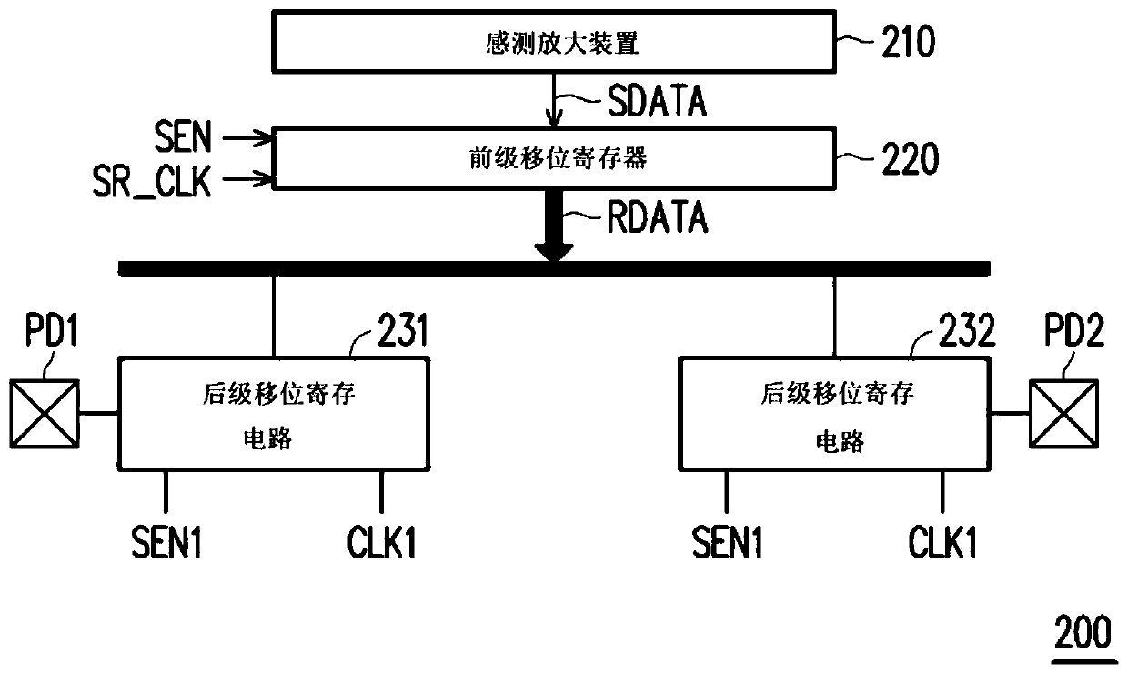
[0042] Please refer to figure 2 , Which is a block diagram of a memory data transmission device according to an embodiment of the present invention. The data transmission device 200 includes a sensing amplification device 210, a previous-stage shift register circuit 220, and a plurality of later-stage shift register circuits 231 to 232. The previous-stage shift register circuit 220 is coupled to the sensing and amplifying device 210 of the memory. The front-stage shift register circuit 220 receives the sensing data SDATA from the sensing amplifier 210 and shifts the sensing data bit by bit according to the shift clock signal SR_CLK to sequentially output a plurality of read data RDATA. The subsequent stage shift register circuits 231 and 232 are coupled to the previous stage shift register circuit 220, and the subsequent stage shift register circuits 231 and 232 are respectively coupled to the pads PD1 and PD2. The pads PD1 and PD2 are input and output (I / O) pads used to conf...


PUM


Abstract

The invention provides a memory data transmission device and a data transmission method thereof. The data transmission device includes a front-stage shift register circuit and a plurality of latter-stage shift register circuits. The front-stage shift register circuit is coupled to the sense amplifier device of the memory, receives the sense data from the sense amplifier device, and shifts out the sense data bit by bit according to the shift clock signal to sequentially output a plurality of read data. A plurality of post-stage shift register circuits are coupled to the pre-stage shift register circuits and are respectively coupled to a plurality of bonding pads. The plurality of post-stage shift register circuits respectively receive the read data and transmit the read data to the pads bit by bit according to the clock signal. Wherein, the frequency of the shifted clock signal is smaller than the frequency of the clock signal.

Description

Technical field [0001] The invention relates to a data transmission device and a data transmission method thereof, in particular to a data transmission device with a two-level structure and a data transmission method thereof. Background technique [0002] Please refer to figure 1 , Which shows a circuit diagram of an existing memory data transmission device. In the prior art, the main array 110 is coupled to the page buffer 120 and provides data for read operation to the sense amplifier 130 through the page buffer 120. The sense amplifier 130 senses the aforementioned data and provides the sensed data to the shift register 140. The shift register 140 receives and latches the sensing data, and shifts out the sensing data bit by bit according to the clock signal CLK, and directly provides the shifted data to the plurality of pads PD1 to PD4. [0003] The budget for data propagation from the shift register 140 to the pads PD1 to PD4 is half the clock cycle (1 / 2CLK). Data propagatio...

Claims


Application Information

Patent Timeline
Patent Type & Authority Patents(China)
IPC IPC(8): G11C19/28
CPCG11C19/28G11C7/1036G11C7/1066G11C7/106G11C7/065G11C7/1006G11C7/22G11C7/1051
Inventor 欧伦麦克李豊烨
Owner WINBOND ELECTRONICS CORP
Why Eureka
Try Eureka