Radiation-resistant optical fiber preparation method
A radiation-resistant, optical fiber preform technology, applied in the field of optical fiber manufacturing, to suppress uneven stress distribution, reduce radiation sensitivity, and achieve the effects of large-scale manufacturing
- Summary
- Abstract
- Description
- Claims
- Application Information
AI Technical Summary
Problems solved by technology
Method used
Image
Examples
preparation example Construction
[0031] Therefore, an embodiment of the present invention provides a method for preparing a radiation-resistant optical fiber, which includes the following steps:
[0032] S1, annealing the optical fiber preform to obtain an annealed optical fiber preform;
[0033]S2, carrying hydrogen on the annealed optical fiber preform to obtain a hydrogen-loaded optical fiber preform;
[0034] S3, performing pre-irradiation on the hydrogen-loaded optical fiber preform to obtain a pre-irradiated optical fiber preform;
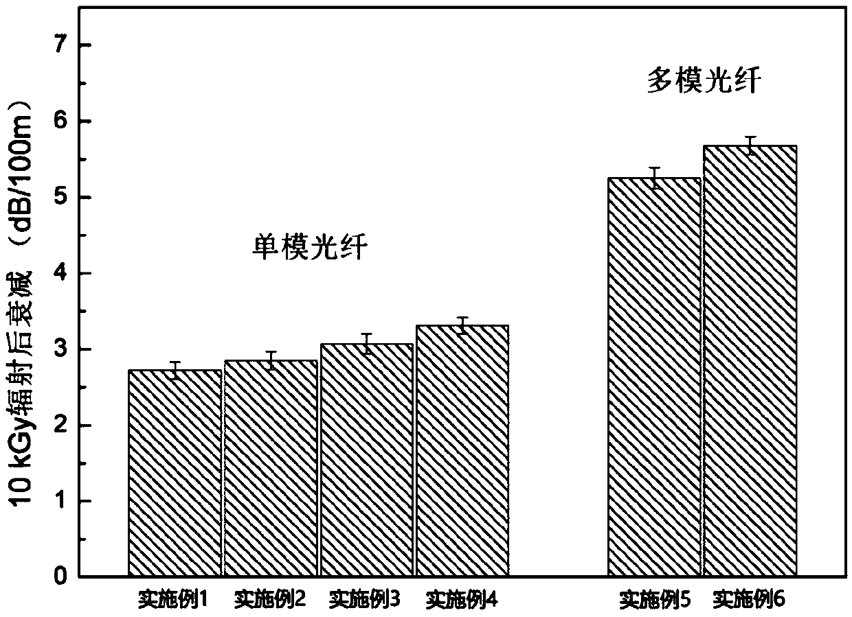
[0035] S4, drawing the pre-irradiated optical fiber preform to obtain a radiation-resistant single-mode optical fiber or a radiation-resistant multi-mode optical fiber.
[0036] The optical fiber preform to be processed in the method of the present invention is a commercial optical fiber preform, and its main component is optical fiber grade high-purity SiO 2 Glass. It is easy to understand that in order to meet the requirements of waveguide structure and optical fiber pe...
Embodiment 1
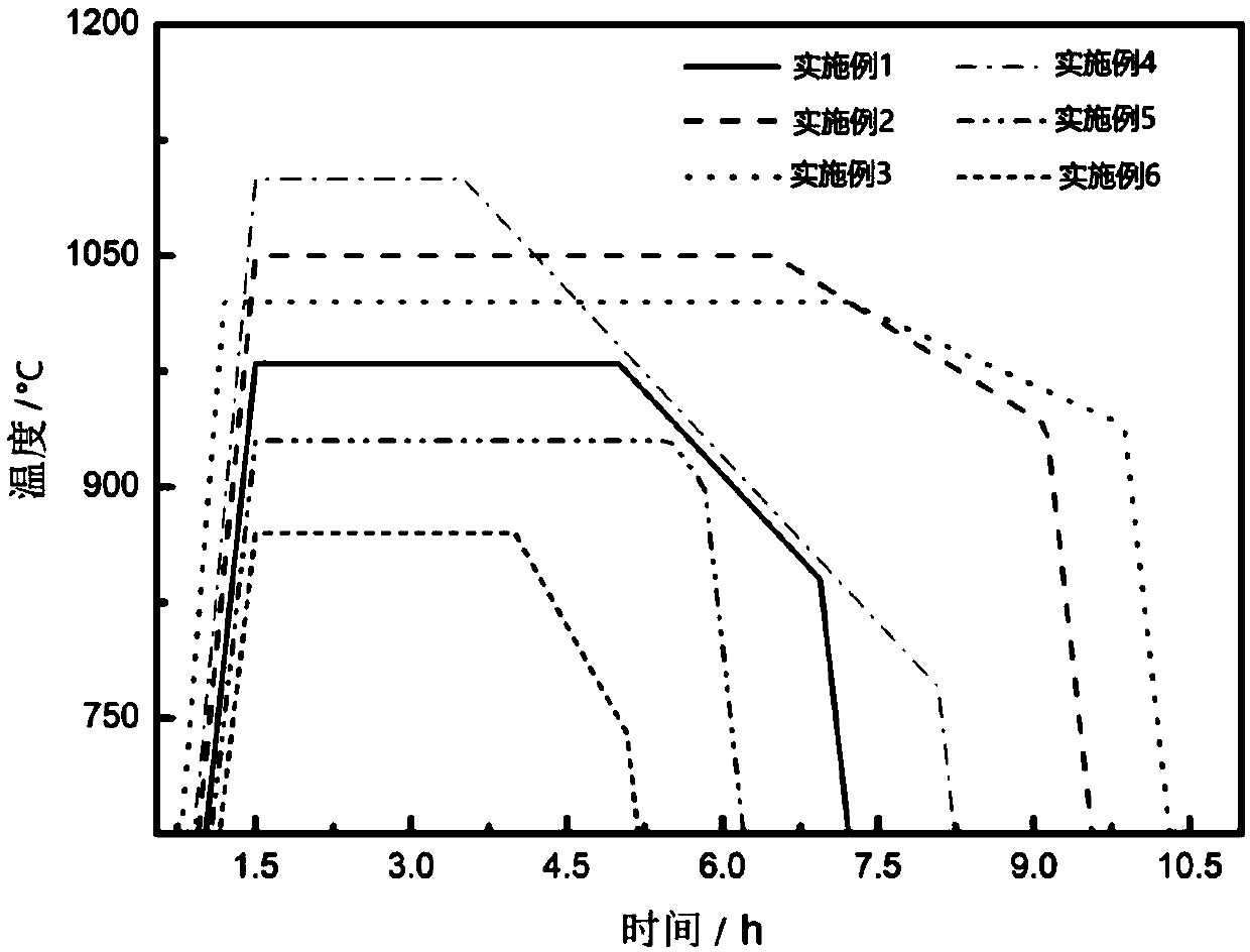
[0056] Select a clean and complete commercial single-mode optical fiber preform with a length of 1050 mm and a diameter of 80 mm, and place it in a box-type resistance furnace. First, the optical fiber preform is heated to the set temperature T 1 =980℃, heat preservation t 1 = After 3.5h, in K 1 =1.2°C / min annealing rate down to target temperature T 2 =840°C, then stop heating and cool down naturally with the furnace. The cooled optical fiber preform is placed in a hydrogen pressure tank, the hydrogen pressure is 1.0 MPa, the hydrogen concentration is greater than 99v%, and the hydrogen loading time is 12 hours. After the hydrogen loading is completed, the optical fiber preform is placed in an irradiation facility under room temperature and air environment for γ-ray pre-irradiation. The radiation dose rate of the optical fiber preform is 50Gy / h, and the total radiation dose is 1.70kGy. After the above pretreatment of the optical fiber preform is completed, the single-mode...
Embodiment 2
[0058] Select a clean and complete commercial single-mode optical fiber preform with a length of 700 mm and a diameter of 72 mm, and place it in a box-type resistance furnace. First, the optical fiber preform is heated to the set temperature T 1 =1050℃, heat preservation t 1 = After 5h, take K 1 =0.7°C / min annealing rate to cool down to target temperature T 2 =940°C, then stop heating and cool down naturally with the furnace. The cooled optical fiber preform is placed in a hydrogen pressure tank, the hydrogen pressure is 1.5MPa, the hydrogen concentration is greater than 99v%, and the hydrogen loading time is 8h. After the hydrogen loading is completed, the optical fiber preform is placed in an irradiation facility under room temperature and air environment for γ-ray pre-irradiation. The radiation dose rate of the optical fiber preform is 85Gy / h, and the total radiation dose is 1.25kGy. After the above pretreatment of the optical fiber preform is completed, the single-mod...
PUM
| Property | Measurement | Unit |
|---|---|---|
| diameter | aaaaa | aaaaa |
| length | aaaaa | aaaaa |
| length | aaaaa | aaaaa |
Abstract
Description
Claims
Application Information
 - Generate Ideas
- Intellectual Property
- Life Sciences
- Materials
- Tech Scout
- Unparalleled Data Quality
- Higher Quality Content
- 60% Fewer Hallucinations
Browse by: Latest US Patents, China's latest patents, Technical Efficacy Thesaurus, Application Domain, Technology Topic, Popular Technical Reports.
© 2025 PatSnap. All rights reserved.Legal|Privacy policy|Modern Slavery Act Transparency Statement|Sitemap|About US| Contact US: help@patsnap.com


