A printing dryer for improving drying effect

A drying machine and printing technology, applied in printing machines, printing, printing devices, etc., can solve the problems of ignoring the drying effect and insufficient drying of fabrics, and achieve the effect of improving the drying effect

Active Publication Date: 2020-07-28
SHAOXING UNIVERSITY
View PDF16 Cites 0 Cited by
  • Summary
  • Abstract
  • Description
  • Claims
  • Application Information

AI Technical Summary

Problems solved by technology

[0003] Chinese patent CN106931753A discloses a drying mechanism in a printing device for printed fabrics, including a drying mechanism. The drying mechanism includes a drying chamber and a second cloth guide roller located in the drying chamber. The second cloth guide roller is hollow and The two ends are an open end and a closed end respectively, and an exhaust port is provided on the side wall of the closed end; a heating barrel is fixed on the top of the drying chamber, and a heater is installed in the heating barrel, and the heater divides the inner cavity of the heating barrel into a cold air chamber and the heating chamber, the heater includes an air channel connecting the cold air chamber and the heating chamber, an exhaust fan is installed in the heating chamber, and two hot air outlets are arranged at the bottom of the heating barrel; The air cylinder, the upper end of the exhaust cylinder communicates with the hot air outlet through the air pipe, and the air inlet pipe is inserted in the opening end, and the outer end of the air inlet pipe extends out of the open end and communicates with another hot air outlet; when drying the fabric, it is often concentrated Dry the middle part of the fabric, while ignoring the drying effect on the side of the fabric, resulting in a certain amount of moisture on the side of the fabric after the middle part of the fabric is dried, resulting in insufficient drying of the fabric

Method used


Image

  • A printing dryer for improving drying effect
  • A printing dryer for improving drying effect
  • A printing dryer for improving drying effect

Examples


Embodiment Construction

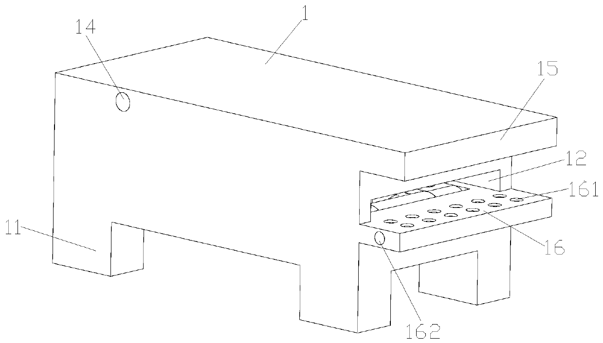
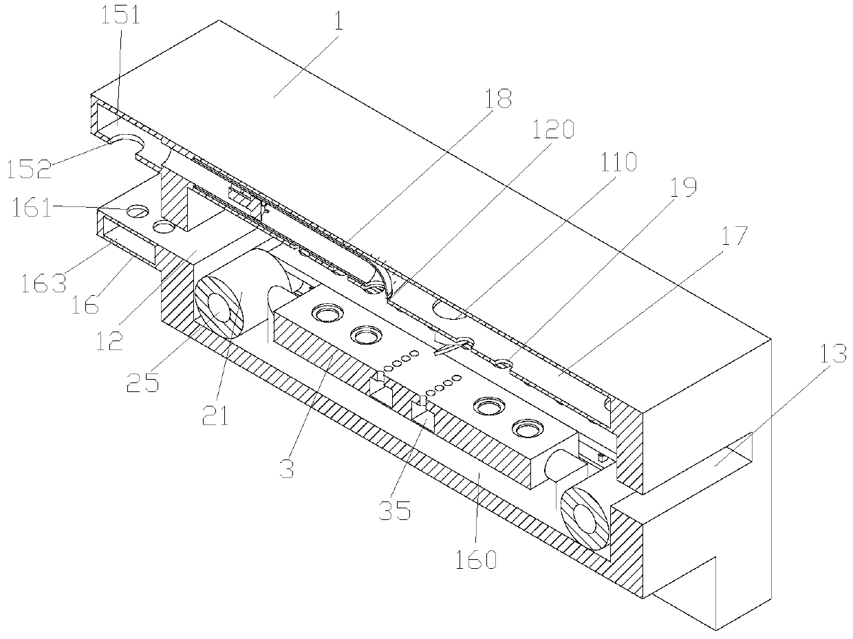
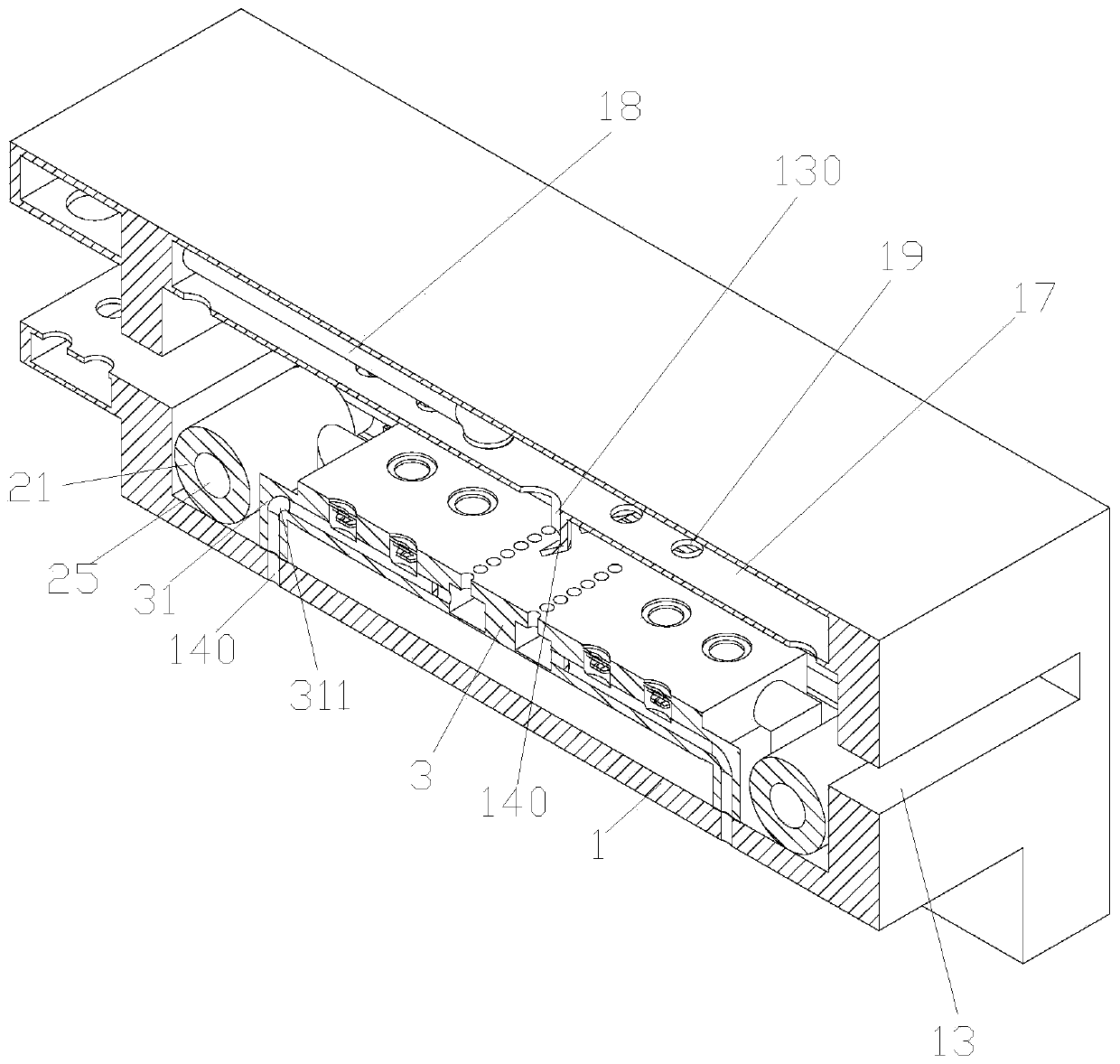
[0026] Such as Figure 1-13As shown, a printing dryer for improving the drying effect, including a box body 1, a support frame 11 arranged at the bottom of the box body 1, and a transmission component arranged in the box body 1, and the support is erected on the box body The four ends at the bottom provide support for the dryer; a drying chamber is provided in the box body 1, and an installation chamber 160 is provided at the bottom of the drying chamber, and the transmission component is arranged in the installation chamber 160, so The side wall of the box body 1 is provided with a material inlet 12, and the other side of the box body 1 is provided with a material outlet 13. , the sleeve 21 arranged on the roller 2 and the conveyor belt 22 arranged on the roller 2, the conveyor belt is made of polyurethane material to avoid damage to the fabric; there are two groups of rollers, respectively located in the installation cavity The two ends are used to fix the conveyor belt; un...


PUM


Abstract

The invention discloses a printing dryer for improving the drying effect, which comprises a box body, a support frame arranged at the bottom of the box body, and a transmission component arranged in the box body, and the box body is provided with a drying machine. chamber, the bottom of the drying chamber is provided with an installation chamber, the transmission component is arranged in the installation chamber, the side wall of the box body is provided with a feed port, and the other side of the box body is provided with an outlet The feed port, the conveying assembly includes a rotating roller rotatably arranged in the installation cavity, a sleeve arranged on the rotating roller and a conveyor belt arranged on the roller, the conveyor belts are divided into two groups, respectively Located on both sides of the rotating roller; the fifth air storage chamber is arranged inside the rotating roller, the sixth air storage chamber communicated with the fifth air storage chamber is arranged on the conveyor belt, and the sixth air storage chamber is arranged on the conveyor belt A sixth air outlet communicating with the sixth air storage chamber.

Description

technical field [0001] The invention belongs to the field of textiles, and in particular relates to a printing dryer for improving the drying effect. Background technique [0002] The printing process is the process of printing patterns on textiles with dyes or pigments; printing can be divided into fabric printing, top printing and yarn printing, and mainly fabric printing; top printing is used to make mixed-color tweed; yarn Printing is used to weave special-style colorful patterned fabrics. After the dyeing paste is sprayed on the fabrics, the fabrics need to be dried before the next steam treatment can be performed on the fabrics. [0003] Chinese patent CN106931753A discloses a drying mechanism in a printing device for printed fabrics, including a drying mechanism. The drying mechanism includes a drying chamber and a second cloth guide roller located in the drying chamber. The second cloth guide roller is hollow and The two ends are an open end and a closed end respect...

Claims


Application Information

Patent Timeline
Patent Type & Authority Patents(China)
IPC IPC(8): B41J11/00B41F23/04
CPCB41F23/04B41J11/002
Inventor 张新华邵舒嘉卢丽娟王秀庆潘露丹何绍木陈坤
Owner SHAOXING UNIVERSITY
Why Eureka
Try Eureka