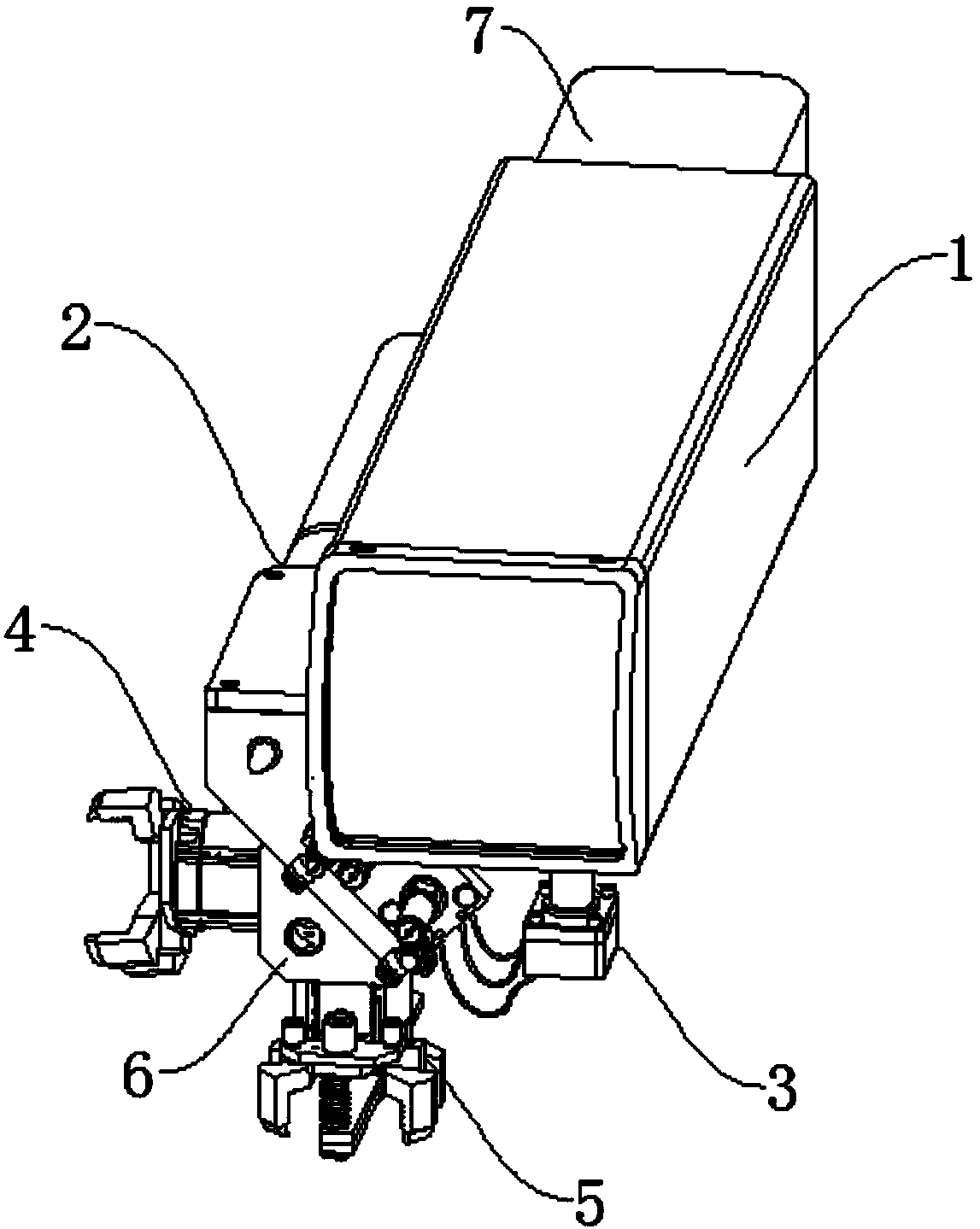
Intelligent manufacturing production line actuator
An intelligent manufacturing and production line technology, applied in the field of actuators, can solve problems such as low execution efficiency, inaccurate judgment of workpiece placement position, and insufficient sensitivity of workpiece recognition, so as to achieve the effect of improving execution efficiency and clamping stability
- Summary
- Abstract
- Description
- Claims
- Application Information
AI Technical Summary
Problems solved by technology
Method used
Image
Examples
Embodiment 1
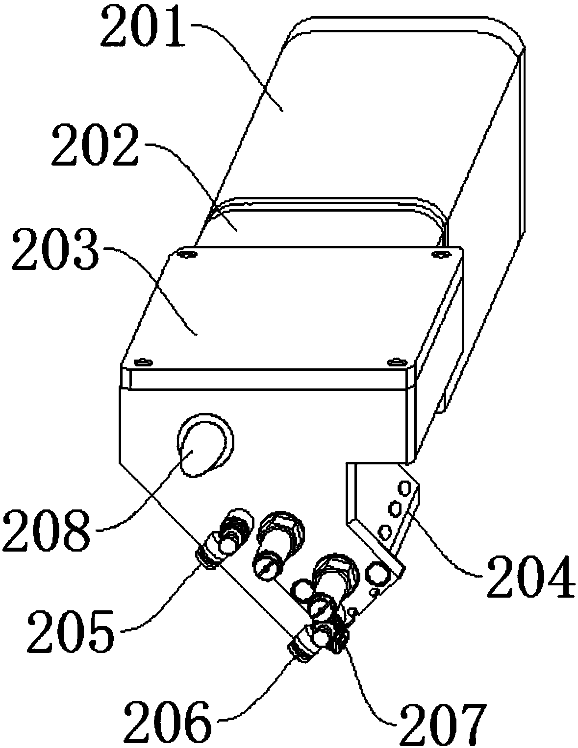
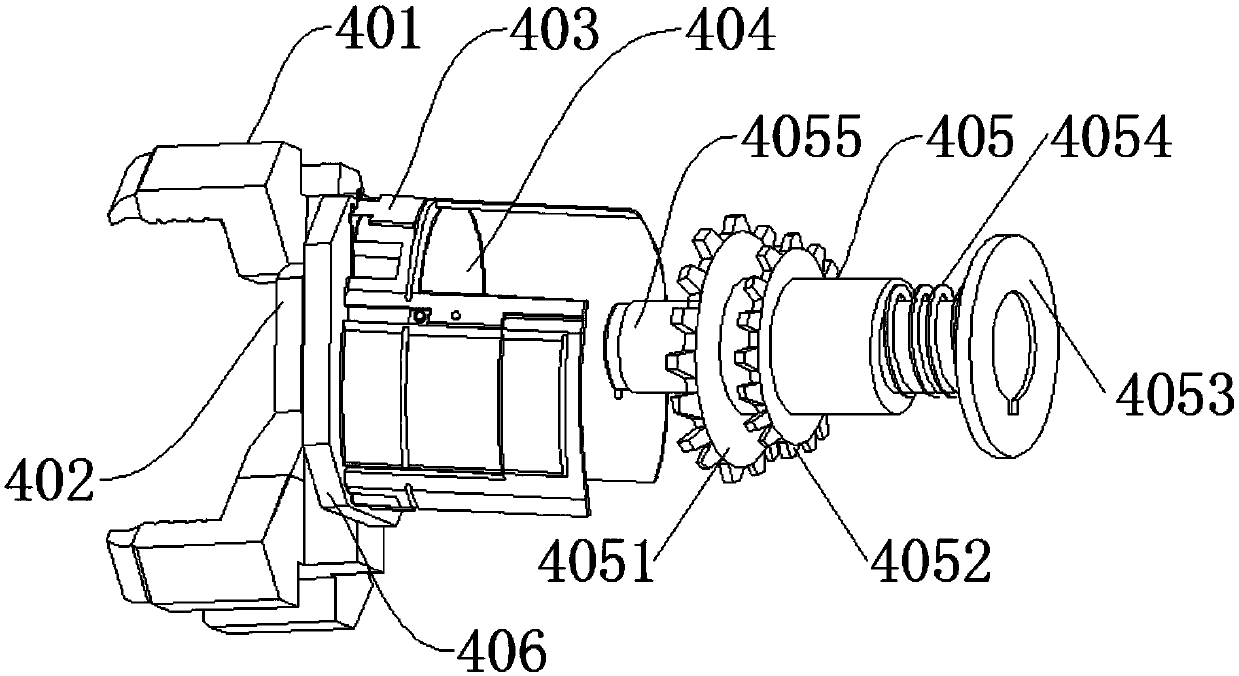
[0028] see Figure 1-4 , a technical solution of the present invention: the horizontal linkage mechanism 4 includes a first mechanical claw 401, a joint 402, an electromagnet 403, a gear seat 404, a reducer 405 and a turntable 406, and the first mechanical claw 401 is installed on one side of the joint 402, The joint 402 is connected to the turntable 406, the inner side of the gear seat 404 is connected to the reducer 405, and there is a gap between the electromagnet 403 and the edge of the turntable 406, and the first mechanical claw 401 and the second mechanical claw 507 are the same by the second motor. 505 cooperates with the gear set to drive, and the second motor 505 drives the forward and reverse rotation of the gear set to realize the contraction and expansion of the four mechanical jaws, which are used for accurate clamping of workpieces in the horizontal direction and improve the efficiency of clamping execution The vertical interlocking mechanism 5 includes the main...
Embodiment 2
[0030] Different from Embodiment 1 and it should be noted that, if Figure 3-4 , after the discharger 504 is discharged, the electromagnetic wire 506 is energized to charge the adsorption sheet 508, so that the adsorption sheet 508 is magnetically attached. The principle is the same as that of the electromagnet. , to improve the clamping stability of the workpiece; at the same time, the reducer 405 includes a primary reduction gear 4051, a secondary reduction gear 4052, a connecting plate 4053, a screw rod 4054 and a movable rod 4055, and the primary reduction gear 4051 and the secondary reduction gear The gear 4052 keeps meshing with the gear seat 404, the connection plate 4053 and the screw mandrel 4054 keep relative movement, and one end of the screw mandrel 4054 is fixedly connected with the connection plate 4053, and the set electromagnet 403 generates repulsion with the gear seat 404 after being electrified. The gear base 404 rotates due to magnetism, and the gear base 4...
Embodiment 3
[0032] The difference from Embodiments 1 and 2 is that the main controller 1 is provided with a corresponding memory stick inside, and after connecting with the junction box 3 through the PLC control, the execution data in the memory stick is sorted out and then executed, and the first motor 503 is electrically controlled , the discharger 504, the second motor 505 and the electrode sheet 403 are executed according to the set program, and the input information obtained by the monitoring of the input circuit is stored in the input mapping area of the PLC and the electrical appliances are operated. After running the user program, the output mapping area will be obtained The transformed information is refreshed by the output, and the output latch will reflect the state of the output mapping area, and generate corresponding output through the output circuit, and its operation law and control method are relatively stable; the first sensor 205, the second sensor 206 and the The thir...
PUM
 Abstract
Description
Claims
Application Information
 - R&D
- Intellectual Property
- Life Sciences
- Materials
- Tech Scout
- Unparalleled Data Quality
- Higher Quality Content
- 60% Fewer Hallucinations
Browse by: Latest US Patents, China's latest patents, Technical Efficacy Thesaurus, Application Domain, Technology Topic, Popular Technical Reports.
© 2025 PatSnap. All rights reserved.Legal|Privacy policy|Modern Slavery Act Transparency Statement|Sitemap|About US| Contact US: help@patsnap.com


