
Hydraulic tool

A tooling and hydraulic technology, applied in the field of hydraulic tooling, can solve the problems of low work efficiency, limited manual clamping and low efficiency, and achieve the effect of ensuring positioning rigidity, high drilling efficiency, and avoiding movement.

Pending Publication Date: 2019-04-05
苏州勤美达精密机械有限公司
View PDF8 Cites 0 Cited by
  • Summary
  • Abstract
  • Description
  • Claims
  • Application Information

AI Technical Summary

Problems solved by technology

[0002] With the continuous development and updating of manufacturing technology, the application of flanges is becoming more and more extensive, and the manufacturing accuracy of flanges is becoming more and more stringent. In order to ensure the accuracy of butt joints, the requirements for the position of screw holes in flanges are becoming more and more difficult. At present, The manufacturing equipment has the problems of low efficiency and limited manual clamping. The application of multi-axis drilling machine can greatly improve the efficiency of flange drilling, but the flange is clamped on the tooling, because the flange positioning needs to occupy at least 100% of the flange. Two holes, resulting in the need for subsequent re-drilling of these two holes, which is time-consuming and laborious, and the work efficiency is low. In view of this, it is necessary to improve the traditional hydraulic tooling

Method used


Image

  • Hydraulic tool

Examples


Embodiment Construction

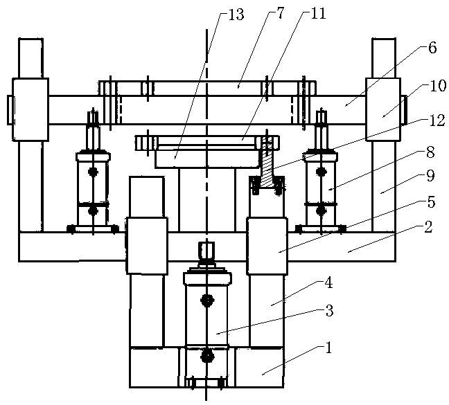
[0014] The present invention will be specifically introduced below in conjunction with the accompanying drawings and specific embodiments.

[0015] see figure 1 , a hydraulic tooling of the present invention, comprising a pressing mechanism and an upward mechanism, the upward mechanism comprises a base 1, a support 2 and a first oil cylinder 3, and both sides of the top of the base 1 are vertically fixed with a first guide column 4, The front end of the support 2 is vertically fixed with two first guide sleeves 5 corresponding to the first guide post 4, the first guide sleeve 5 is correspondingly sleeved on the first guide post 4, and the bottom end of the first oil cylinder 3 is fixed on the base 1 The middle part of the top, its top is fixedly connected with the middle part of the bottom end of the support 2, and the extension and contraction of the first oil cylinder 3 drive the support 2 to move up and down.

[0016] The pressing mechanism comprises a pressing plate 6, a ...


PUM


Abstract

The invention discloses a hydraulic tool. The hydraulic tool comprises a downward pressing mechanism and an upward jacking mechanism. The upward jacking mechanism comprises a base, a support and a first oil cylinder. The two sides of the top end of the base are both perpendicularly and fixedly provided with first guide pillars. The front end of the support is perpendicularly and fixedly provided with two first guide sleeves corresponding to the first guide pillars. The first guide pillars are sleeved with the first guide sleeves correspondingly. The bottom end of the first oil cylinder is fixed to the middle portion of the top end of the base. The top end of the first oil cylinder is fixedly connected with the middle portion of the bottom end of the support. The first oil cylinder stretches and retracts to drive the support to move up and down. The downward pressing mechanism comprises a pressing plate, a guide hole plate and two second oil cylinders. The bottom ends of the two secondoil cylinders are perpendicularly fixed to the two sides of the top of the support. The top ends of the two second oil cylinders are fixed to the two sides of the bottom of the pressing plate. The second oil cylinders stretch and retract to drive the pressing plate to move up and down. The hydraulic tool can effectively and firmly clamp a flange to prevent the flange from moving in the drilling process and moreover can complete machining of all holes through a multi-spindle drill bit.

Description

technical field [0001] The invention belongs to the technical field of mechanical processing, and in particular relates to a hydraulic tooling. Background technique [0002] With the continuous development and updating of manufacturing technology, the application of flanges is becoming more and more extensive, and the manufacturing accuracy of flanges is becoming more and more stringent. In order to ensure the accuracy of butt joints, the requirements for the position of screw holes in flanges are becoming more and more difficult. At present, The manufacturing equipment has the problems of low efficiency and limited manual clamping. The application of multi-axis drilling machine can greatly improve the efficiency of flange drilling, but the flange is clamped on the tooling, because the flange positioning needs to occupy at least 100% of the flange. Two holes cause these two holes to be drilled later, which is time-consuming and laborious, and the work efficiency is low. In v...

Claims


Application Information

Patent Timeline
Patent Type & Authority Applications(China)
IPC IPC(8): B23Q3/08B23B47/28
CPCB23B47/28B23Q3/08B23Q3/082
Inventor 杨程
Owner 苏州勤美达精密机械有限公司
Learn More