
Differential evolution algorithm-based CRS dip decomposition method

A differential evolution algorithm and population technology, applied in the field of oil and gas exploration seismic data processing, can solve the problems of image quality reduction, three-parameter test infinite coherence value is impractical, affect the stacking section effect, etc., and achieve the effect of improving the effect

Active Publication Date: 2019-04-02
CHINA UNIV OF PETROLEUM (EAST CHINA)
View PDF3 Cites 3 Cited by
  • Summary
  • Abstract
  • Description
  • Claims
  • Application Information

AI Technical Summary

Problems solved by technology

[0004] The CRS stacking method enhances the continuity of the reflection event and the signal-to-noise ratio on the stacked section. The conventional parameter selection is to test all parameters, and the selected α, R NIP , and R N has the largest coherence value, however it is obviously impractical to test the coherence value infinitely for the three parameters
In the conventional parameter search, the exit angle α is searched first, and then R is searched based on the determination of α NIP and R N , so this method results in that at each point in the stacked section, only the strongest reflection energy from a certain angle can be selected, while the reflection information and diffraction information of other angles will be eliminated by interference, resulting in the kinematic characteristics of the CRS stacked section distortion
Especially in areas with complex structures or well-developed abnormal waves, due to the lack of diffraction energy after CRS stacking, the effect of stacking sections is seriously affected, and the quality of subsequent seismic migration imaging will also be reduced. Therefore, this problem affects the CRS stacking method. Practicality
Two-dimensional CRS stacking can obtain high-quality imaging results under complex geological conditions. However, since three-dimensional CRS stacking requires three subsurface wave field parameters, the results of three-dimensional CRS stacking are greatly affected by the parameters.

Method used


Image

  • Differential evolution algorithm-based CRS dip decomposition method
  • Differential evolution algorithm-based CRS dip decomposition method
  • Differential evolution algorithm-based CRS dip decomposition method

Examples


Embodiment 1

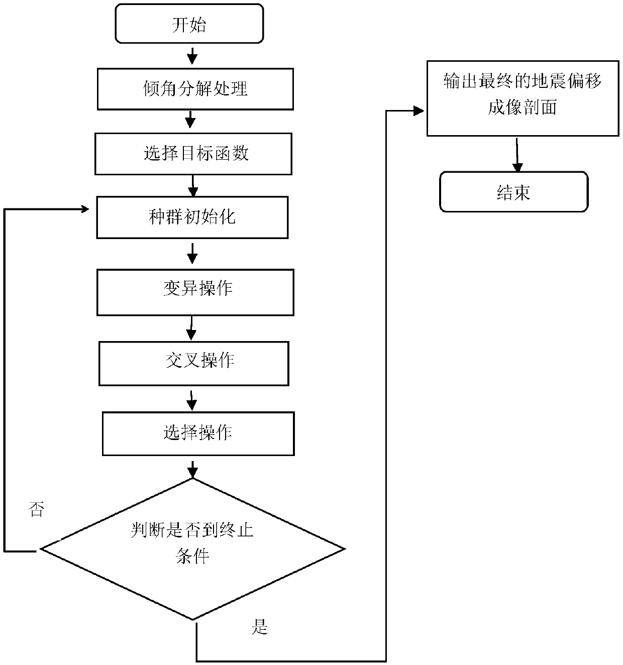
[0039] Such as figure 1 As shown, a CRS inclination angle decomposition method based on differential evolution algorithm is completed by discretizing the outgoing angle α, and the inclination angle is divided into several parts. For each part, the parameters with the highest similarity are obtained based on the differential evolution algorithm. Finally, each part partially superimposed.

[0040] Before the dip division process, in order to improve the R in the search space NIP The lower limit of , the minimum dynamic correction speed is required, and the lower limit is calculated by the minimum dynamic correction speed

[0041]

[0042] lb is denoted as the lower boundary, α min and alpha max is the boundary of the angle range, v 0 is the ground velocity, V min is the dynamic correction speed, similarly, the maximum dynamic correction speed can be used to calculate R NIP The upper limit of , where the CRS motion correction velocity is obtained using the CRS parameters...


PUM


Abstract

The invention belongs to the field of oil-gas exploration seismic data processing, and specifically relates to a differential evolution algorithm-based CRS dip decomposition method. According to the method, a dip is divided into a plurality of parts through dispersing an emergence angle alpha, a parameter with a highest similarity is obtained for each part on the basis of a differential evolutionalgorithm, and finally the parts are superposed. According to the differential evolution algorithm-based CRS dip decomposition method, in order to solve coherent values of three independent variablesalpha, RNIP and RN, a correlation coefficient for balancing the sizes of the coherent values is used as a target function to search three parameters. An angle parameter range of the whole search spaceis divided into relatively small parts, so that event information which interferes mutually to cause shielding can be recognized. Through combining dip division with a global optimization scheme, complicated subsurface structure conditions are effectively restored and the effect of common reflection surface superposition is improved.

Description

technical field [0001] The invention belongs to the field of oil and gas exploration seismic data processing, and in particular relates to a CRS dip angle decomposition method based on a differential evolution algorithm. Background technique [0002] In the late 1980s, Professor Hubral in Germany proposed the Common Reflection Surface CRS (Common Reflection Surface CRS) technology, referred to as CRS superposition. The CRS stacking method does not need any assumptions about the shape of the subsurface medium, nor does it need to obtain a velocity model. It makes full use of the coherence of seismic waves and is applicable to both uniform and non-uniform subsurface media. Within the range of the stacking aperture, the energy in the adjacent gathers is stacked as much as possible to enhance the seismic signal energy, which can effectively improve the processing quality of low signal-to-noise ratio seismic data. Through CRS stacking, not only high-quality zero-offset profiles ...

Claims


Application Information

Patent Timeline
IPC IPC(8): G01V1/30
Inventor 孙小东宋煜依尔繁贾延睿李振春
Owner CHINA UNIV OF PETROLEUM (EAST CHINA)
Learn More