Bent axle box ventilation labyrinth

A crankcase ventilation and labyrinth technology, which is used in crankcase ventilation, engine components, machines/engines, etc., can solve the problems of long distance, high cost and complex structure of oil baffles, and increase the contact area and the number of collisions. , the effect of improving the effect

Active Publication Date: 2011-01-12
CHERY AUTOMOBILE CO LTD
View PDF5 Cites 5 Cited by
  • Summary
  • Abstract
  • Description
  • Claims
  • Application Information

AI Technical Summary

Problems solved by technology

[0002] In the crankcase ventilation labyrinth of the existing structure, the separation of oil and gas is formed by arranging the oil baffle to make the oil gas flow along the wall surface and adsorbing on the wall surface, and by changing the direction of the air flow, the oil in the oil gas is separated by centrifugation. The distance between the oil-retaining baffles is far away, so that the effect of oil and gas flowing along the wall and the effect of turning the airflow are not obvious, and the effect of oil-gas separation is not very good. In addition, in order to increase the contact area between the airflow and the baffles, it is necessary to increase the number of baffles, and the cost is high
When the oil-air separation efficiency of the labyrinth is not high, it is necessary to add an additional oil-air separator to separate the oil, increasing parts and costs
In addition, the original labyrinth also needed to design a separate oil return channel and take oil and gas isolation measures, which also resulted in a more complicated structure.

Method used


Image

  • Bent axle box ventilation labyrinth
  • Bent axle box ventilation labyrinth
  • Bent axle box ventilation labyrinth

Examples


Embodiment Construction

[0013] The present invention will be described in detail below in conjunction with specific embodiments and accompanying drawings.

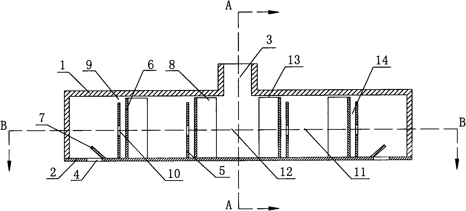
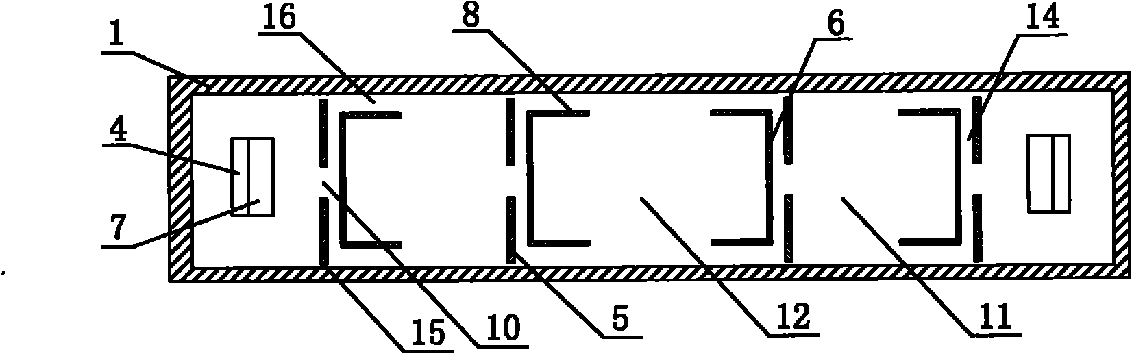
[0014] Such as figure 1 , 2 , 3, the main body of the crankcase ventilation labyrinth of the present embodiment is a cuboid cavity surrounded by the valve chamber cover 1 and the coaming plate 2, the top center of the main body has an air outlet 3, and the bottom two sides have Air inlet 4; two groups of partitions are arranged at intervals between the air outlet 3 and each air inlet 4, and each group of partitions consists of a first partition 5 near the direction of the air inlet 4 and a second partition near the direction of the air outlet 3. Composed of plates 6, the distance between the first partition 5 and the second partition 6 is 2-10 mm; there is a first air gap 9 of 1-10 mm between the top of the first partition 5 and the cover plate of the valve chamber cover 1, A through hole 10 with a diameter of 1-15mm is opened in the center of ...


PUM

PropertyMeasurementUnit
Diameteraaaaaaaaaa

Abstract

The invention provides a bent axle box ventilation labyrinth with simple structure and good oil gas separating effect. The main body of the labyrinth is a cuboid cavity; the main body has an air outlet and an air inlet; multiple groups of diaphragms are arranged between the air inlet and the air outlet in the cavity at intervals; each group of diaphragms is composed of a first diaphragm close to the direction of the air inlet and a second diaphragm close to the direction of the air outlet; the distance of the first diaphragm and the second separation is 2-10mm; a first gas passing clearance is arranged between the top part of the first diaphragm and the top plate of the main body; a through hole is arranged at the center of the first diaphragm; a second gas passing clearance is arranged between the side of the diaphragm and the side plate of the main body; oil returning holes are arranged at the bottoms of the first diaphragm and the second diaphragm; the bent axle box ventilation labyrinth of the invention utilizes the clearances formed between the inner wall of the main body and the diaphragm and between the diaphragms as oil and gas flowing channels to lead oil and gas to flow in the narrow clearances, thus increasing the contact areas and crashing times between the oil and gas and the diaphragm as well as between the oil and gas and the inner wall of the main body, and improving the effect of oil and gas separation.

Description

technical field [0001] The invention belongs to a crankcase ventilation system in the field of engines, in particular to a crankcase ventilation labyrinth in the crankcase ventilation system. Background technique [0002] In the crankcase ventilation labyrinth of the existing structure, the separation of oil and gas is formed by arranging the oil baffle to make the oil gas flow along the wall surface and adsorbing on the wall surface, and by changing the direction of the air flow, the oil in the oil gas is separated by centrifugation. The distance between the oil-retaining baffles is far away, so that the effect of oil-gas flow along the wall and the effect of airflow turning are not obvious, and the effect of oil-gas separation is not very good. In addition, in order to increase the contact area between the airflow and the baffles, it is necessary to increase the number of baffles, and the cost is high . When the oil-gas separation efficiency of the labyrinth is not high, ...

Claims


Application Information

Patent Timeline
IPC IPC(8): F01M13/04
Inventor 王志高高建鹏
Owner CHERY AUTOMOBILE CO LTD
Why Eureka
Try Eureka