
Automotive tyre pattern depth detector

A technology for pattern depth and automobile tires, applied in mechanical depth measurement, instruments, measuring devices, etc., can solve the problems of detection deviation, inaccurate reading data, low efficiency, etc., to achieve accurate reading, improve accuracy, improve The effect of measuring efficiency

Inactive Publication Date: 2019-04-02
陕西迈拓克能源科技有限公司
View PDF0 Cites 12 Cited by
  • Summary
  • Abstract
  • Description
  • Claims
  • Application Information

AI Technical Summary

Problems solved by technology

[0006] In order to solve the above problems, the present invention provides an automobile tire tread depth detector, which can solve the problem that the existing tire tread depth is usually measured by personnel through the tread wear scale, and personnel may not be inserted vertically or to the deepest depth , will lead to deviations in the detection, and the personnel can only read the amount on the spot, the reading data may be inaccurate, and when the ruler is inserted, the gravel particles stuck in the pattern may affect the accuracy of the measurement, and the detection efficiency is low, etc. It can realize the function of accurately measuring the tire tread depth, vertically insert different tire treads to the end, and fix the detection rod after the depth detection, so that it is convenient for personnel to pick up and read carefully, the reading is accurate, and the measurement efficiency is improved.

Method used


Image

  • Automotive tyre pattern depth detector
  • Automotive tyre pattern depth detector
  • Automotive tyre pattern depth detector

Examples


Embodiment Construction

[0040]Embodiments of the present invention will be described below with reference to the drawings. In the process, in order to ensure the clarity and convenience of illustration, we may exaggerate the width of the lines or the size of the constituent elements in the diagram.

[0041] In addition, the following terms are defined based on the functions in the present invention, and may be different according to the user's or operator's intention or practice. Therefore, these terms are defined based on the entire content of this specification.

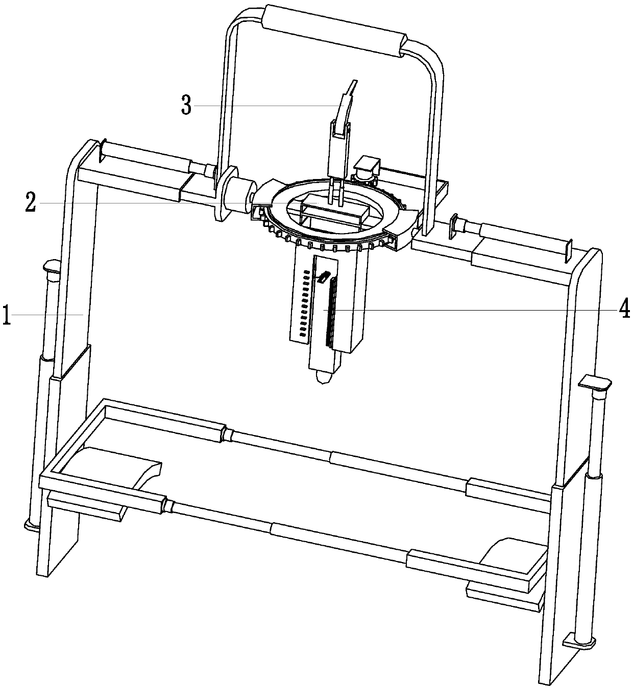
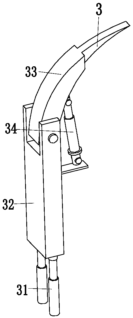
[0042] Such as Figure 1 to Figure 6 As shown, an automobile tire pattern depth detector includes a clamping adjustment device 1, a bracket 2, a crushed stone particle extraction device 3 and a detection device 4. The middle part of the clamping adjustment device 1 is equipped with a bracket 2, and the bracket The upper end of the bracket 2 is equipped with a crushed stone digging device 3, and the lower end of the support 2 is equipped...


PUM


Abstract

The invention relates to an automotive tyre pattern depth detector comprising a clamping adjusting device, a bracket, a small broken stone scratching device and a detecting device. The bracket is installed at the middle part of the clamping adjusting device; the small broken stone scratching device is installed at the upper end of the bracket; and the detecting device is installed at the lower endof the bracket. At present, when existing tyre pattern depth detection is carried out, the worker uses a pattern wear scaleplate to carry out measurement; the offset is caused easily when no verticalinsertion or sufficient insertion at the maximum depth is performed in a manual insertion mode; only on-site measurement by the worker is required and the read and measured data have low accuracy; and when the scaleplate is inserted, the small broken stones clamped in the pattern may affect the measurement accuracy, so that the detection efficiency is low. However, with the automotive tyre pattern depth detector, problems can be solved; the tyre pattern depth can be measured accurately; sufficient vertical insertion of different tyre patterns is realized; and a detection rod is fixed after depth detection, so that the worker can read the number conveniently after taking the rod and reading is carried out accurately.

Description

technical field [0001] The invention relates to the field of tire detection, in particular to an automobile tire tread depth detector. Background technique [0002] Car tires are one of the important parts of the car. They are in direct contact with the road, and work with the car suspension to ease the impact of the car while driving, so as to ensure that the car has good ride comfort and smooth driving. The tires need to be inspected regularly Avoid the emergence of safety hazards caused by tire aging. [0003] Among them, the tire tread detection is an inspection of the tire self-inspection. The tire tread is too small or worn to the prompt line and needs to be replaced in time. The existing tire tread depth detection is usually measured by personnel through the tread wear scale. However, there are The following defects: 1. When the personnel insert, they may not be inserted vertically or to the deepest depth, which will lead to deviations in the detection; 2. The person...

Claims


Application Information

Patent Timeline
IPC IPC(8): G01B5/18G01B5/00
CPCG01B5/18G01B5/0002G01B5/0025
Inventor 萧飞
Owner 陕西迈拓克能源科技有限公司
Learn More