
Ultrasonic transducer scanning system, method and ultrasonic imaging equipment

A technology of ultrasonic transducer and scanning system, applied in ultrasonic/sonic/infrasonic equipment control, ultrasonic/sonic/infrasonic diagnosis, sonic diagnosis, etc. The effect of improving accuracy

Active Publication Date: 2022-05-27
CHISON MEDICAL TECH CO LTD
View PDF9 Cites 0 Cited by
  • Summary
  • Abstract
  • Description
  • Claims
  • Application Information

AI Technical Summary

Problems solved by technology

[0002] At present, when medical staff perform ultrasound imaging diagnosis on patients, the medical staff will use one hand to hold the transducer, and then place it on the part that needs to be examined for scanning and imaging, and control it on the ultrasound host with the other hand, which is very inconvenient
At present, there are still some devices that fix the ultrasonic transducer on a support arm, and then manually move the medical staff to the examination site for examination. For example, during breast examination, the medical staff will move the transducer module to the patient through the support arm. Scanning is performed on the breast, however, this method still allows the operator to move the ultrasound transducer to find the target cross-sectional image

Method used


Image

  • Ultrasonic transducer scanning system, method and ultrasonic imaging equipment
  • Ultrasonic transducer scanning system, method and ultrasonic imaging equipment
  • Ultrasonic transducer scanning system, method and ultrasonic imaging equipment

Examples


Embodiment Construction

[0046] The specific embodiments of the present invention will be described in detail below with reference to the accompanying drawings. It should be understood that the specific embodiments described herein are only used to illustrate and explain the present invention, but not to limit the present invention.

[0047] Furthermore, each term such as "...unit", "...device" and "means", as described in the specification, denotes an element for performing at least one function or operation, and may be implemented in hardware, software and / or hardware and software combination. The term "ultrasound image" as used herein refers to an image of an object acquired by using ultrasound. The term "object" as used herein may include animate or inanimate things, and an object may refer to a part of the human body and may include organs or blood vessels such as liver, heart, uterus, brain, breast, abdomen, and the like. Additionally, the term "user" as used herein may include medical profess...


PUM


Abstract

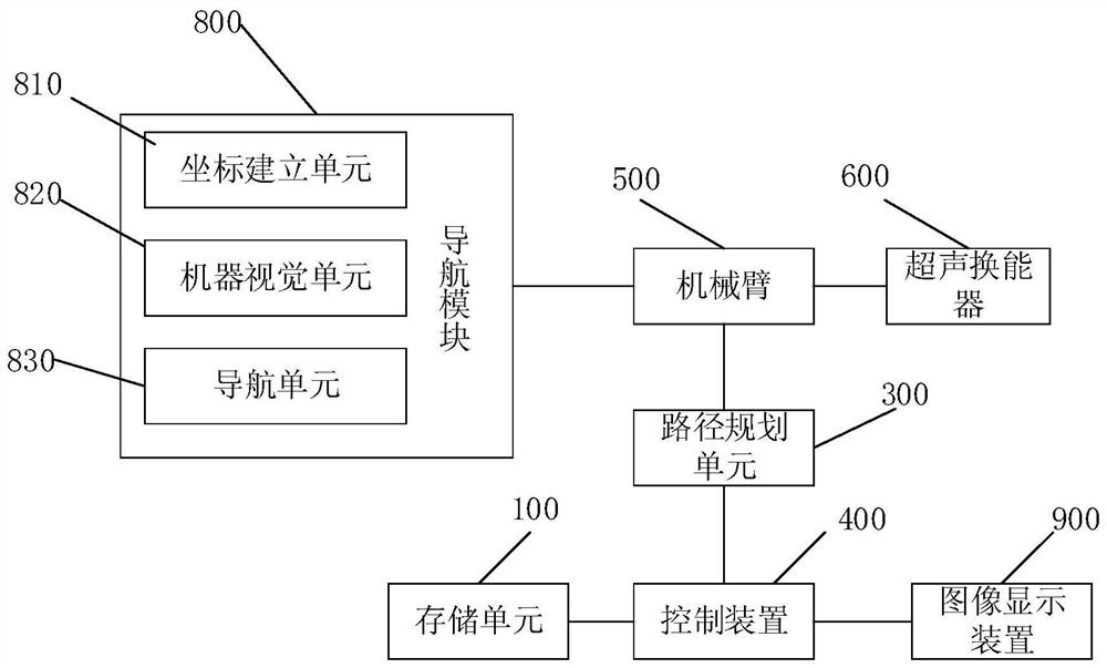
The invention relates to the technical field of ultrasonic imaging equipment, and specifically discloses an ultrasonic transducer scanning system. The invention includes a robot arm, a storage unit, a path generation unit and a control device. The end of the mechanical arm is provided with an ultrasonic transducer, so that the ultrasonic transducer can move and scan the surface of the target part to be inspected. The storage unit stores reference cross-sectional images corresponding to different target parts. The path generation unit generates moving path information according to the initial cross-sectional image collected by the ultrasonic transducer and the reference cross-sectional image. The control device controls the mechanical arm and the ultrasonic transducer to perform motion scanning according to the moving path information to obtain the target cross-sectional image. The invention also provides a scanning method and an ultrasonic imaging device. For example, during breast examination, the transducer module is moved to the patient's breast through the support arm for scanning. The invention can automatically acquire the target cross-sectional image of the target part that needs to be inspected, has a high degree of automation, and greatly improves the imaging efficiency.

Description

technical field [0001] The present invention relates to the technical field of ultrasonic imaging equipment, in particular to an ultrasonic transducer scanning system, method and ultrasonic imaging equipment. Background technique [0002] At present, when medical staff perform ultrasound imaging diagnosis on patients, medical staff will use one hand to hold the transducer, then place it on the part to be examined for scanning and imaging, and use the other hand to control the ultrasound host, which is very inconvenient. At present, there are still some devices that fix the ultrasonic transducer on a support arm, and then manually move it to the examination site by the medical staff for examination. For example, during breast examination, the medical staff will move the transducer module to the patient through the support arm. The scan is performed on the breast, however, this way the operator still moves the ultrasound transducer to find the target cross-sectional image. ...

Claims


Application Information

Patent Timeline
Patent Type & Authority Patents(China)
IPC IPC(8): A61B8/00
CPCA61B8/4218A61B8/4411A61B8/4483A61B8/54
Inventor 莫若理赵明昌王勇
Owner CHISON MEDICAL TECH CO LTD
Learn More