
Steam valve, steam valve control method, and cooking utensil

A technology for cooking utensils and a control method, which is applied to the cover of cooking utensils, the structure of cooking utensils, cooking utensils, etc., can solve the problems of lack of rice fragrance, reducing the competitiveness of product time, reducing cooking effect, etc., to ensure safe use performance, The effect of improving the taste of rice and enhancing the cooking effect

Active Publication Date: 2019-04-02
FOSHAN SHUNDE MIDEA ELECTRICAL HEATING APPLIANCES MFG CO LTD
View PDF8 Cites 8 Cited by
  • Summary
  • Abstract
  • Description
  • Claims
  • Application Information

AI Technical Summary

Problems solved by technology

[0002] At present, the existing electric rice cooker, the upper cover of the electric rice cooker is equipped with a steam valve or a vent hole, so that the water vapor generated by the electric cooker during the cooking process can be discharged smoothly, but the vent hole and the existing steam valve are normally open. structure, which makes the inner pot of the rice cooker always in a state of communication with the outside world during each stage of the cooking process, that is, in the stage of stewing rice or keeping warm, the steam channel is open, so that the steam in the rice cooker and the aroma of food Loss, so that the rice becomes dry and has no rice flavor, which greatly reduces the cooking effect, affects the user experience, and reduces the competitiveness of the product for a long time

Method used


Image

  • Steam valve, steam valve control method, and cooking utensil
  • Steam valve, steam valve control method, and cooking utensil
  • Steam valve, steam valve control method, and cooking utensil

Examples


Embodiment Construction

[0053] In order to understand the above-mentioned purpose, features and advantages of the present invention more clearly, the present invention will be further described in detail below in conjunction with the accompanying drawings and specific embodiments. It should be noted that, in the case of no conflict, the embodiments of the present application and the features in the embodiments can be combined with each other.

[0054] In the following description, many specific details are set forth in order to fully understand the present invention, but the present invention can also be implemented in other ways different from those described here, therefore, the protection scope of the present invention is not limited to the specific details disclosed below. EXAMPLE LIMITATIONS.

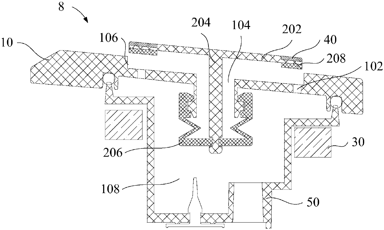
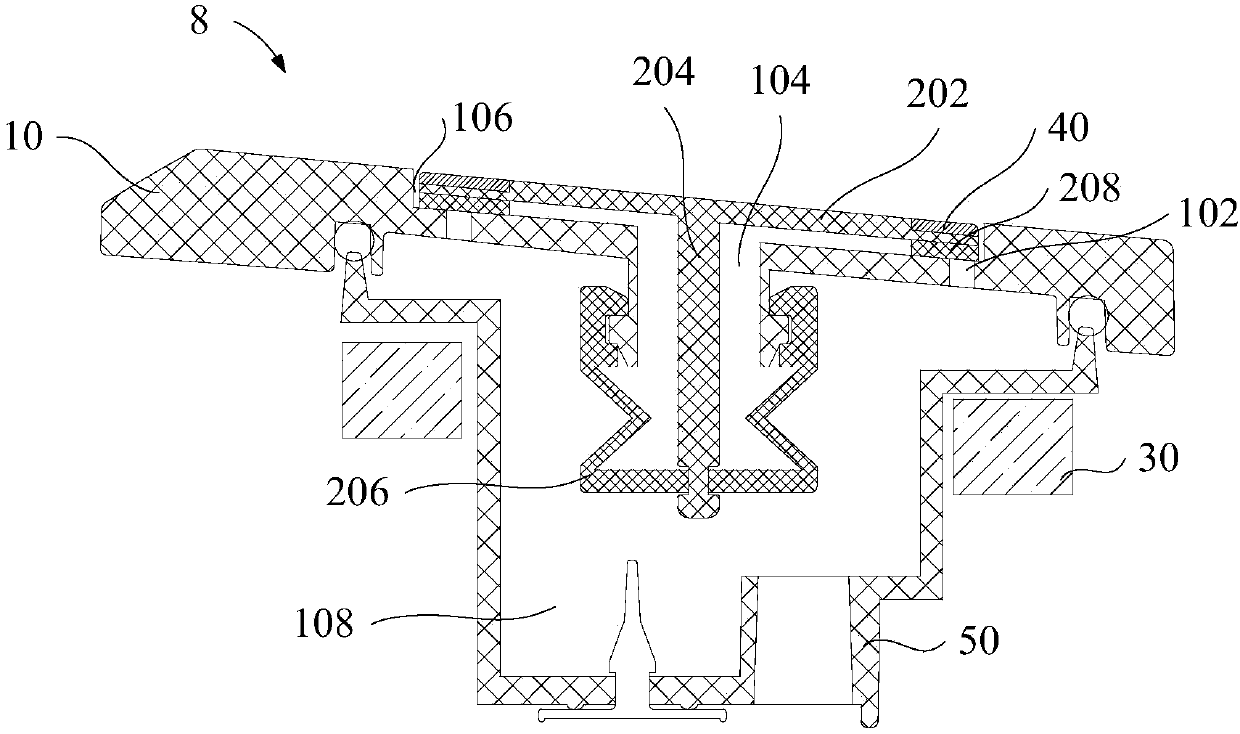
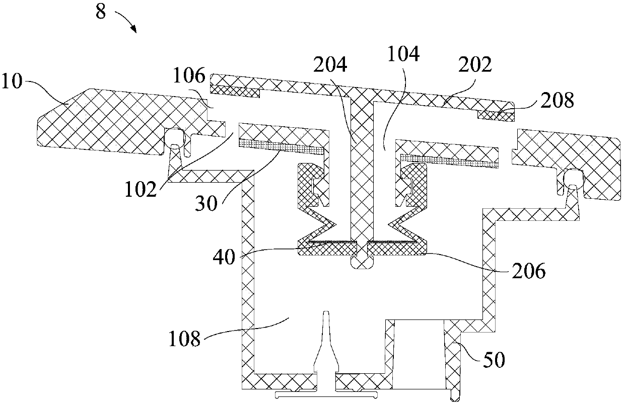
[0055] A first aspect of the invention, figure 1 and figure 2 A longitudinal sectional view of a steam valve in an embodiment of the present invention is shown. According to one aspect of the present ...


PUM


Abstract

The invention provides a steam valve used for a cooking utensil. The cooking utensil comprises a control plate, and the steam valve; the steam valve comprises a valve seat, a valve cover, a floating member, an electromagnetic member, and a reset member; the valve cover is provided with at least one steam vent and a conducting hole; a cavity is formed through enclosing of the valve cover and the valve seat; the floating member comprises a floating cover and a floating column; the floating cover is arranged above the valve cover, and is connected with the floating column; the floating column ismovably arranged in the conducting hole; the electromagnetic member is connected with the valve seat or the valve cover; the reset member is arranged on the floating member; the control plate is connected with the electromagnetic member through electric connection, and is used for sending control signals to the electromagnetic member; the electromagnetic member is used for generating magnetic force for adsorption or repulsion of the reset member based on the control signals, so that sealing of the floating member with the valve cover is realized. According to the steam valve control method, the electromagnetic member and the reset member are adopted, so that the sealing effect of the cooking utensil is improved, the floating cover is pressed against the valve cover firmly, no steam or fragrance loss in the cooking utensil is caused, cooked rice drying is prevented, cooking effect is improved, and the mouthfeel of cooked rice is improved.

Description

technical field [0001] The present invention relates to the technical field of kitchen appliances, in particular to a steam valve, a steam valve control method and a cooking utensil. Background technique [0002] At present, the existing electric rice cooker, the upper cover of the electric rice cooker is equipped with a steam valve or a vent hole, so that the water vapor generated by the electric cooker during the cooking process can be discharged smoothly, but the vent hole and the existing steam valve are normally open. structure, which makes the inner pot of the rice cooker always in a state of communication with the outside world during each stage of the cooking process, that is, in the stage of stewing rice or keeping warm, the steam channel is open, so that the steam in the rice cooker and the aroma of food Loss, so that the rice becomes dry and has no rice flavor, which greatly reduces the cooking effect, affects the user experience, and reduces the competitiveness o...

Claims


Application Information

Patent Timeline
IPC IPC(8): A47J36/38A47J36/06A47J27/00
CPCA47J27/002A47J36/06A47J36/38
Inventor 刘化勇黄韦铭马利罗飞龙梁志佳
Owner FOSHAN SHUNDE MIDEA ELECTRICAL HEATING APPLIANCES MFG CO LTD
Learn More