Biomass hydrolytic acidification process

A technology of hydrolysis, acidification and biomass, applied in waste fuel, fermentation and other directions, can solve the problem of slow hydrolysis and acidification of straw, and achieve the effect of increasing the crushing force

Inactive Publication Date: 2019-03-29
孙勇
View PDF0 Cites 0 Cited by
  • Summary
  • Abstract
  • Description
  • Claims
  • Application Information

AI Technical Summary

Problems solved by technology

[0006] In order to make up for the deficiencies of the prior art and solve the problem of slow hydrolysis and acidification of crop straws; the present invention proposes a biomass hydrolysis and acidification process

Method used


Image

  • Biomass hydrolytic acidification process
  • Biomass hydrolytic acidification process
  • Biomass hydrolytic acidification process

Examples


Embodiment approach

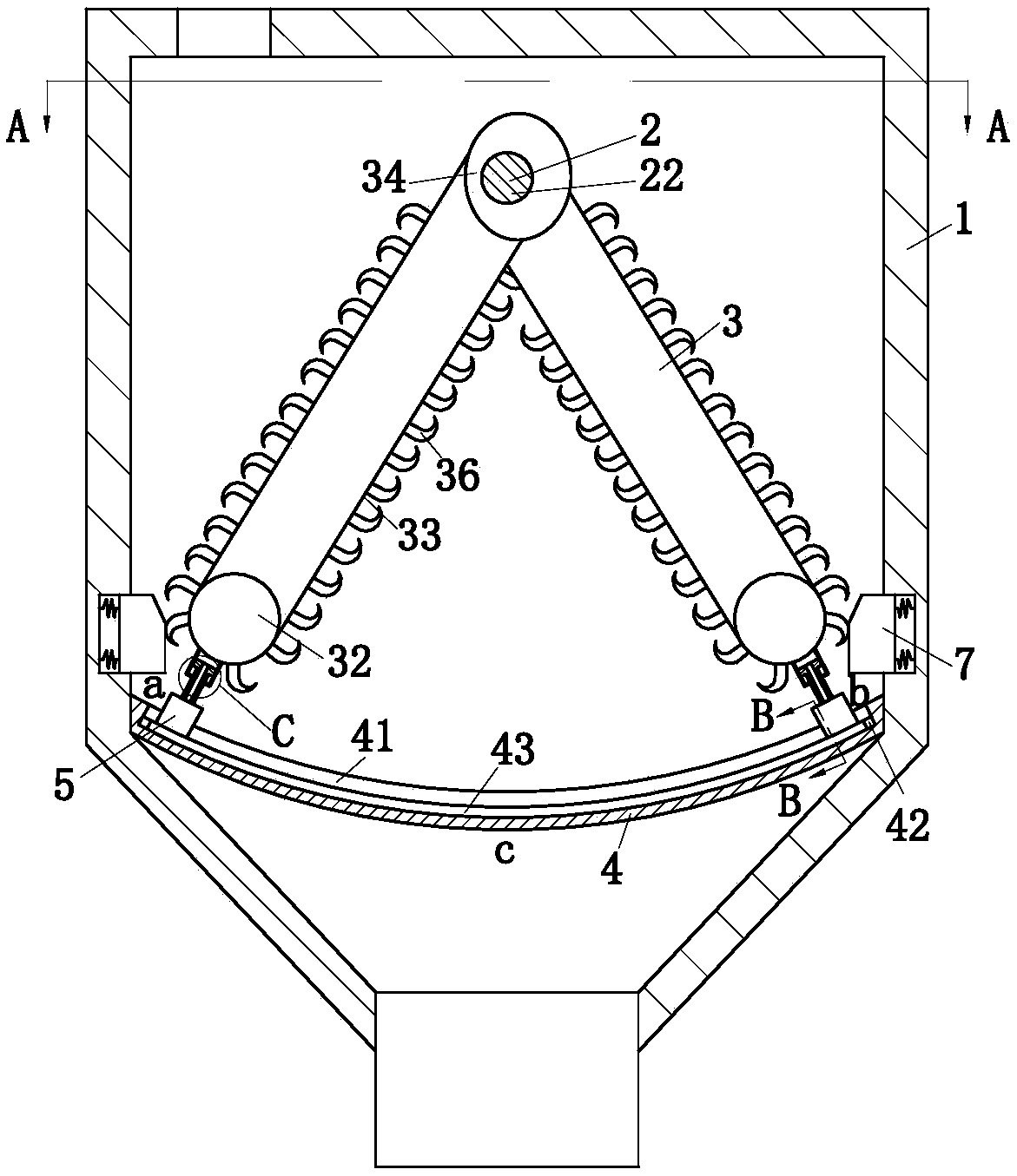
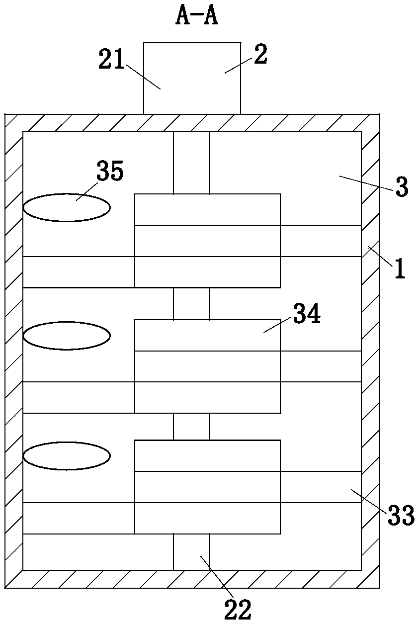
[0043] As an embodiment of the present invention, the No. 1 slider 5 is provided with a No. 1 channel 51; the piston plate in the No. 1 cylinder 6 is provided with a No. 2 channel 61; the arc plate 4 is provided with a No. 3 channel. Passage 44; said No. 1 passage 51, No. 2 passage 61 and No. 3 passage 44 communicate with each other. When the stirring unit 3 slides in the arc-shaped groove 41 through the No. 1 slider 5, the No. 1 cylinder 6 blows air outwards, The bulging gas is transported into the tank body 1 through the connected No. 1 channel 51 , No. 2 channel 61 and No. 3 channel 44 to aerate the biomass in the tank body 1 . In the present invention, through the mutual cooperation between the stirring unit 3, the No. 1 cylinder 6, the arc plate 4, the No. 1 slider 5 and the long balloon 43, the No. 1 cylinder 6 is squeezed and stretched, and the No. 1 cylinder 6 bulges outward. The bulging gas is sprayed to the tank body 1 through the connected No. 1 channel 51, No. 2 ch...


PUM


Abstract

The invention belongs to the technical field of hydrolytic acidification of biomass, and in particular, relates to a biomass hydrolytic acidification process; a hydrolytic acidification device adoptedin the process includes a tank body, a driving unit, a stirring unit, an arc-shaped plate, a No.1 sliding block, a No.1 gas cylinder and a controller. According to the process, on one hand, with interaction of a heating pipe, a pump and a sprayer, the hydrolytic acidification temperature of crop straw in the tank body is maintained at 32-38 DEG C; on the other hand, through interaction of the pump, bean curd residue and the stirring unit, the pH value in the tank body can be adjusted, so that the hydrolytic acidification pH value of the crop straw in the tank body can be maintained at 6.5-7.5; through adjustment of the temperature and the pH value, the influence on hydrolytic acidification of the crop straw due to the temperature and the pH value can be avoided, the hydrolytic acidification of the crop straw is allowed to be fast, and thus the hydrolytic acidification efficiency of the crop straw is improved.

Description

technical field [0001] The invention belongs to the technical field of biomass hydrolysis acidification, and specifically relates to a biomass hydrolysis acidification process. Background technique [0002] Crop straw energy utilization technology is one of the effective ways to alleviate the three crises of "food, energy, and environment" that our country is facing today. Anaerobic fermentation technology has attracted wide attention as the main utilization technology of biomass energy. Anaerobic fermentation technology can be divided into single-phase anaerobic fermentation technology, two-phase anaerobic fermentation technology, mixed anaerobic fermentation technology. Among them, the acid-producing stage and the methanogenic stage in the two-phase anaerobic fermentation process are two independent processing units, each forming the best ecological conditions for acid-producing fermentation microorganisms and methanogenic microorganisms, so that they can exert their maxim...

Claims


Application Information

Patent Timeline
IPC IPC(8): C12P5/02
CPCC12P5/023C12P2203/00Y02E50/30
Inventor 孙勇吴爱兵
Owner 孙勇
Why Eureka
Try Eureka