
An Optimal Design Method for Inflatable Wing

An optimized design and wing technology, which is applied to wings, aircraft parts, ground devices, etc., can solve the problems that the lift-drag ratio of the inflated wing is greatly affected, and there are few researches on the conformal design and shape optimization of the inflated wing. Achieve the effect of keeping the shape of the wing, reducing the number of braces, and improving the lift-to-drag ratio

Active Publication Date: 2020-09-18
CHINA ACAD OF AEROSPACE AERODYNAMICS
View PDF4 Cites 0 Cited by
  • Summary
  • Abstract
  • Description
  • Claims
  • Application Information

AI Technical Summary

Problems solved by technology

[0005] At present, the research on inflatable wings at home and abroad mainly takes the stretched inflatable wing as the research object, focusing on the lightweight material of the inflatable wing, internal structure design, structural aerodynamic integration design, bending, vibration performance and inflatable wing. In the flight test of UAVs, there are few studies on the conformal design and shape optimization of inflated wings.
In addition, for the inflated structure of the inflated wing, it is easy to produce a large deformation under the action of the internal air pressure, and the current method of conformal design by controlling the number of inscribed circles to approach the standard airfoil has an impact on the lift-drag ratio of the inflated wing Larger, it needs to be optimized

Method used


Image

  • An Optimal Design Method for Inflatable Wing
  • An Optimal Design Method for Inflatable Wing
  • An Optimal Design Method for Inflatable Wing

Examples


Embodiment Construction

[0032] Below in conjunction with accompanying drawing, the present invention is described in further detail:

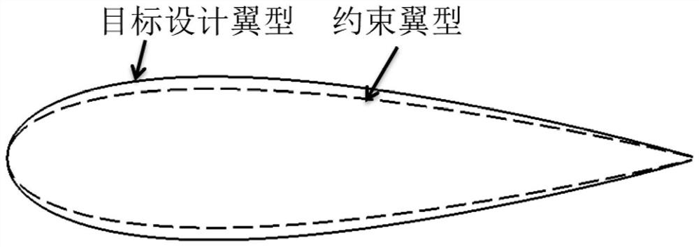
[0033] When optimizing the design of the inflated wing, the parameters of the inflated wing are determined according to the specific parameters of the target wing, mainly including the span length, chord length, sweep angle and section airfoil, etc. The cross-sectional airfoil is determined as the target design airfoil for the inflated wing.

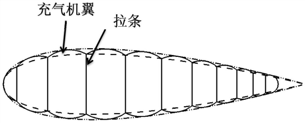
[0034] When using the inscribed circle to approach the target design airfoil, such as figure 1 As shown, a constrained airfoil with the same chord length and different thickness is added to the target design airfoil, so that the intersection of adjacent inscribed circles is located on the constrained airfoil, specifically as figure 2 As shown, the number, position and length of the inscribed circles are controlled by controlling the thickness of the constrained airfoil. Two adjacent circular arc intersections are connected by...


PUM


Abstract

The invention discloses an optimized design method of an inflatable wing, which specifically comprises the following steps of: determining each index parameter of the inflatable wing according to a target design wing, wherein the chord and span length of the wing and the like are included; adding a constraint airfoil with the same chord wise length and different thicknesses in a target design airfoil, so that the intersection points of adjacent inscribed circles are on the constraint airfoil, controlling the position, the number of the inscribed circles and the length of a stay by controllingthe thickness of the constraint airfoil. The design wing with inscribed circle approximation is rectified, and the local depression area of the inflatable wing is smoothed by the skin. the section constraint airfoil of the inflatable wing is the same as the chord length of the target design airfoil, and the thickness of the inflatable wing is 0.75-0.95 of the thickness of the target design airfoil; when an inscribed circle is adopted to approach a target design airfoil, the number of the inscribed circles is between 7-19, determined by the operability and convenience of machining and the sizeof the target design airfoil.

Description

technical field [0001] The invention relates to an optimal design method of an inflatable wing, belonging to the technical field of wing design. Background technique [0002] The inflatable structure shows its use value in the aerospace field due to its light weight, small storage volume and convenient portability. Conventional bracing type inflatable wing is exactly a kind of typical multi-cavity inflatable structure. The United States was the first to apply the inflatable wing technology to the aerospace field. After that, Switzerland, Japan and other countries conducted research on the inflatable wing. [0003] With the introduction of the concept of unmanned aerial vehicles, the heating up of its research, the development of inflatable technology, material technology, stiffening technology, processing technology and control technology, the inflatable wing unmanned aerial vehicle has aroused people's widespread popularity due to its unique characteristics. focus on. Ma...

Claims


Application Information

Patent Timeline
Patent Type & Authority Patents(China)
IPC IPC(8): B64F5/00B64C3/30
CPCB64C3/30B64F5/00
Inventor 喻海川闫溟
Owner CHINA ACAD OF AEROSPACE AERODYNAMICS
Learn More