


Quick Research
Generate reliable direction feasibility study reports for your R&D in just a few steps.

Technical Q&A
Discover and master advanced knowledge NOW. Basics, ideas, possibilities, all at once.

Find Solutions
As an expert in R&D theories, this can generate solutions to your technical problems instantly.

Evaluate Feasibility
Analyze your overall solution with one click, know your potential R&D risks in advance.

Monitor Landscape
Get weekly tech updates, stay abreast of the latest tech innovations and key insights.
Rotary electric trimmer inner cutter head
A trimmer and rotary technology, applied in metal processing and other directions, can solve problems such as poor sound and sharpness, nasal cavity strain, and inability to install multiple cutter heads, achieving high sound consistency, improving shaving comfort, and shaving at the same time Good axis and sharpness
- Summary
- Abstract
- Description
- Claims
- Application Information
AI Technical Summary
Problems solved by technology
Method used
Image

Examples
Embodiment 1
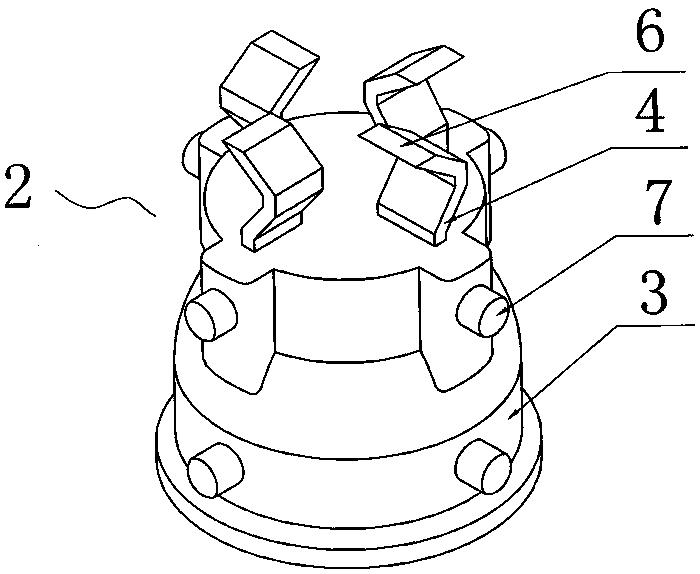
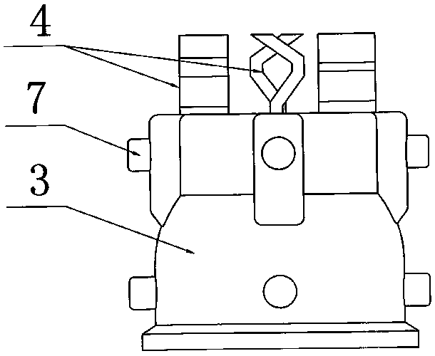
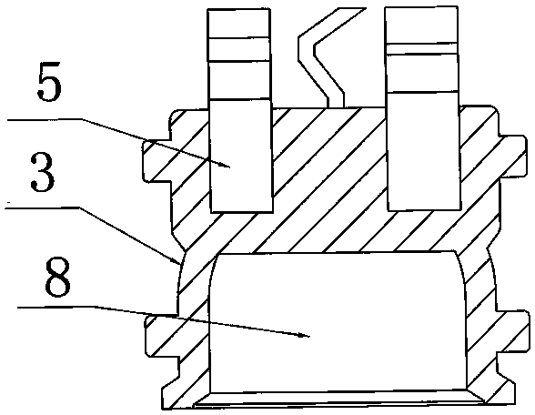
[0016] Embodiment 1: As shown in the accompanying drawings, a rotary electric trimmer inner cutter head includes an outer cutter 1 and an inner cutter 2, and the inner cutter 2 includes a plastic part 3 and four blades 4, and the blades 4 Fixedly connected with the connecting piece 3, the blade 4 includes a connecting portion 5, and the connecting portion 5 is fixedly inserted into the matching slot provided in the plastic part 3, and the upper end of the blade 4 is provided with a blade 6, the The plastic part 3 is provided with 8 protrusions 7 which are socketed with the outer knife 1. The protrusions 7 are arranged in two rows up and down, and 4 of each row are evenly distributed on the outer ring of the plastic part 3. Also be provided with the groove 8 that connects linkage shaft. The height of the outer knife 1 is 3mm shorter than the height of the inner knife 2 . The inner blade height of the rotary electric trimmer is 11mm.
Embodiment 2
[0017] Embodiment 2: Another internal cutter head of a rotary electric trimmer, including an outer cutter 1 and an inner cutter 2, the inner cutter 2 includes a plastic part 3 and two blades 4, and the height of the outer cutter 1 is higher than that of the inner cutter 2 1mm shorter. The inner blade height of the rotary electric trimmer is 10mm.
[0018] Embodiment 2: Another inner cutter head of a rotary electric trimmer, including an outer cutter 1 and an inner cutter 2, the inner cutter 2 includes a plastic part 3 and six blades 4, and the height of the outer cutter 1 is higher than that of the inner cutter 2 4mm shorter. The inner blade height of the rotary electric trimmer is 13mm.
PUM
 Abstract
Description
Claims
Application Information
 - R&D Engineer
- R&D Manager
- IP Professional
- Industry Leading Data Capabilities
- Powerful AI technology
- Patent DNA Extraction
Browse by: Latest US Patents, China's latest patents, Technical Efficacy Thesaurus, Application Domain, Technology Topic, Popular Technical Reports.
© 2024 PatSnap. All rights reserved.Legal|Privacy policy|Modern Slavery Act Transparency Statement|Sitemap|About US| Contact US: help@patsnap.com