
Stereoscopic video collection system

A technology for stereoscopic video and acquisition system, applied in stereoscopic systems, image communication, electrical components, etc., can solve the problems of inaccurate parallax range, no consideration of stereoscopic display device parameters, difficulty in obtaining video parallax range, etc.

Inactive Publication Date: 2019-03-26
ZHEJIANG FUTURE TECH INST JIAXING
View PDF6 Cites 6 Cited by
  • Summary
  • Abstract
  • Description
  • Claims
  • Application Information

AI Technical Summary

Problems solved by technology

[0006] (1) It is difficult to obtain the video parallax range. Usually, the video scene changes a lot. If you only analyze the parallax of a few frames in the video, the obtained parallax range is inaccurate.
Even if the parallax is analyzed for a single frame, it may be inaccurate due to the limitations of the scene and the algorithm;
[0007] (2) There are many kinds of commonly used stereoscopic video display devices, and the post-processing method may appear that no matter how the video parallax is adjusted, there will be a problem that does not match the display parameters, thereby causing the algorithm to fail;
[0008] (3) Even if there are no defects (1) and defects (2), the post-processing method of adjusting parallax will cause video resolution loss
The acquisition system uses the acquisition server to perform post-correction and stereoscopic video synthesis on the acquired images. The synthesized video does not consider the parameters of the stereoscopic display device, which will still cause poor stereoscopic display effects.

Method used


Image

  • Stereoscopic video collection system
  • Stereoscopic video collection system
  • Stereoscopic video collection system

Examples


Embodiment Construction

[0020] In order to make the object, technical solution and advantages of the present invention clearer, the present invention will be further described in detail below in conjunction with the accompanying drawings and embodiments. It should be understood that the specific embodiments described here are only used to explain the present invention, and do not limit the protection scope of the present invention.

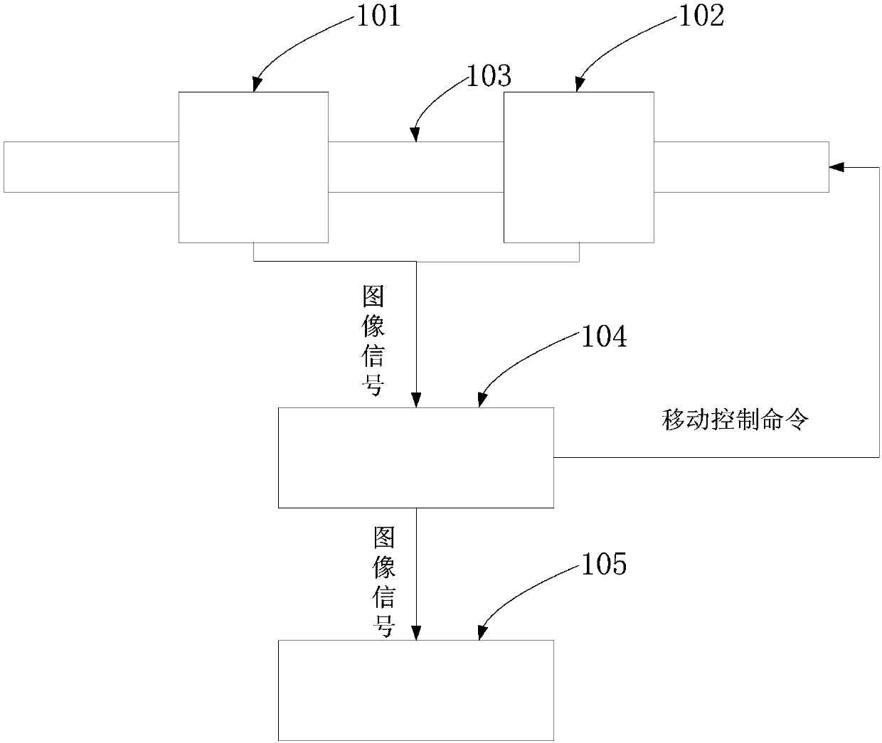
[0021] In order to improve the stereoscopic video display effect, this embodiment provides figure 1 The stereoscopic video acquisition system shown includes a left view image sensor 101 , a right view image sensor 102 , a controllable rail 103 , a processing and controller 104 , and a display device 105 .

[0022] The left view image sensor 101 and the right view image sensor 102 are used to collect the left view image and the right view image of the scene, which are fixed on the displacement slider of the precision electric translation platform, and the position of the ...


PUM


Abstract

The invention discloses a stereoscopic video collection system. The system includes left and right view image sensors, which have controlled and adjustable display windows, and collect left and rightview images of a scene; a controllable guide rail, which is connected with the left and right view image sensors, and controls horizontal movement of the left and right view image sensors under driving of movement control commands; a processing and control device, which determines an optimal image fusion parallax range according to a display device parameter, calculates and obtains an image parallax graph according to collected left and right view images, then judges, according to the optimal image fusion parallax range and image parallax graph, whether the left and right view images need to be adjusted, and calculates parallax adjustment offset quantity when adjustment is needed, generating a movement control command according to the parallax adjustment offset quantity, and sending the same to the controllable guide rail, and directly outputs the left and right view images when adjustment is not needed; and a display device, which receives the left and right view images output by theprocessing and control device, and carries out stereoscopic display. The system imports a stereoscopic video display effect.

Description

technical field [0001] The invention relates to the technical field of stereoscopic video, in particular to a stereoscopic video acquisition system. Background technique [0002] Stereoscopic video is an important direction for the development of multimedia technology in the future, and is now widely used in the advertising industry, product display, film industry and other fields. Good stereoscopic video display effect has been an urgent pursuit in this field. [0003] At present, the principle of stereoscopic video display is mainly based on binocular parallax; the image on the left is input to the left eye, and the image on the right eye is input to the right eye, and the stereoscopic effect is formed in the brain through the parallax of the two eyes. Among them, the principle of naked-eye 3D display is to adjust the angle of light transmission, so that the left and right images are respectively projected into the left and right eyes of the person. Therefore, for the di...

Claims


Application Information

Patent Timeline
IPC IPC(8): H04N13/239H04N13/296H04N13/128H04N13/122
Inventor 邵航张新费回
Owner ZHEJIANG FUTURE TECH INST JIAXING
Learn More