
Battery pack

A battery pack and cell technology, applied in the field of battery packs, can solve the problems of complex process and misplacement, and achieve the effect of simplifying the production process, reducing the manufacturing cost, simplifying the structure and the production process

Inactive Publication Date: 2019-03-26
GUANGZHOU XIAOPENG MOTORS TECH CO LTD
View PDF6 Cites 2 Cited by
  • Summary
  • Abstract
  • Description
  • Claims
  • Application Information

AI Technical Summary

Problems solved by technology

This process requires two upper and lower brackets, and the fit gap between the bracket and the battery needs to be strictly controlled. The assembly process needs to flip the battery, and the process is more complicated.
In particular, double-sided aluminum wire welding is required. The positive and negative electrodes of the battery need to be placed alternately on the front and back, and there is also a risk of misplacement.

Method used

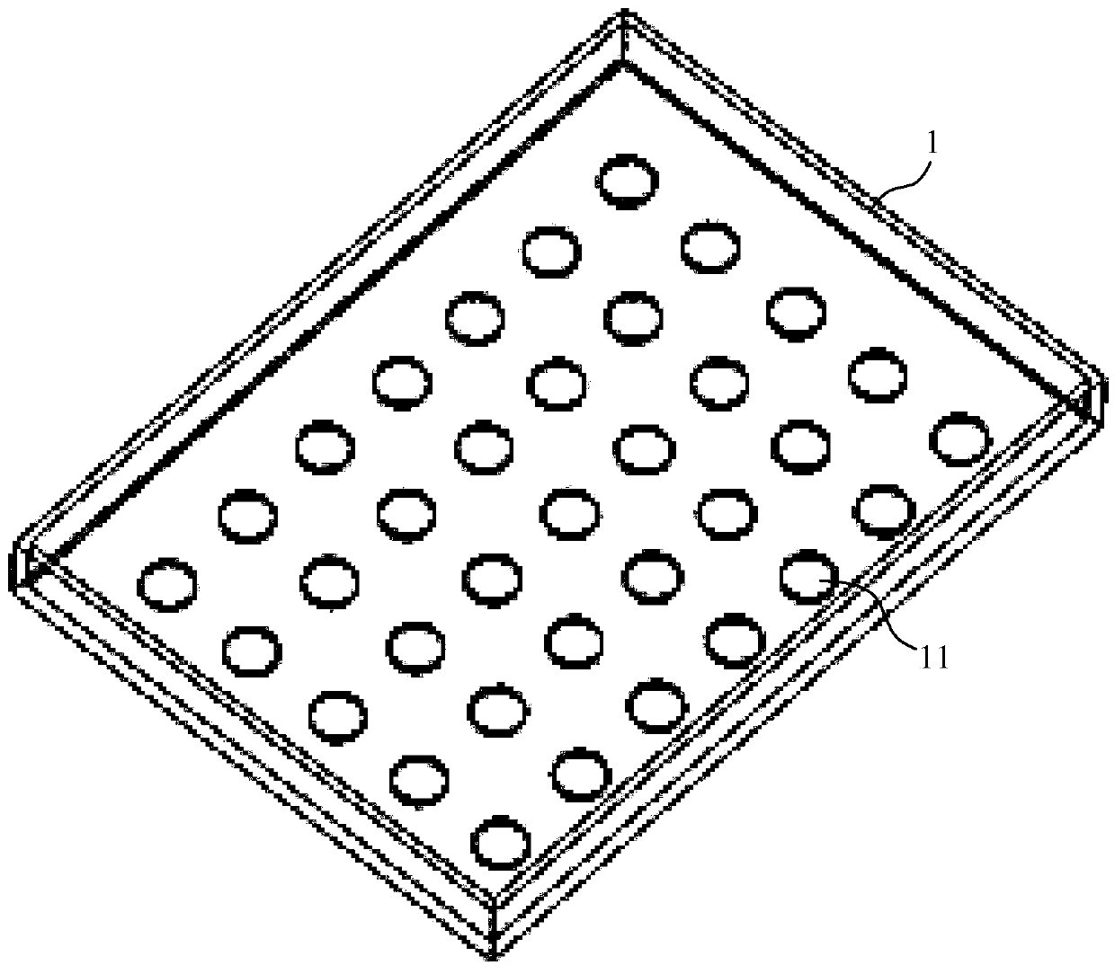
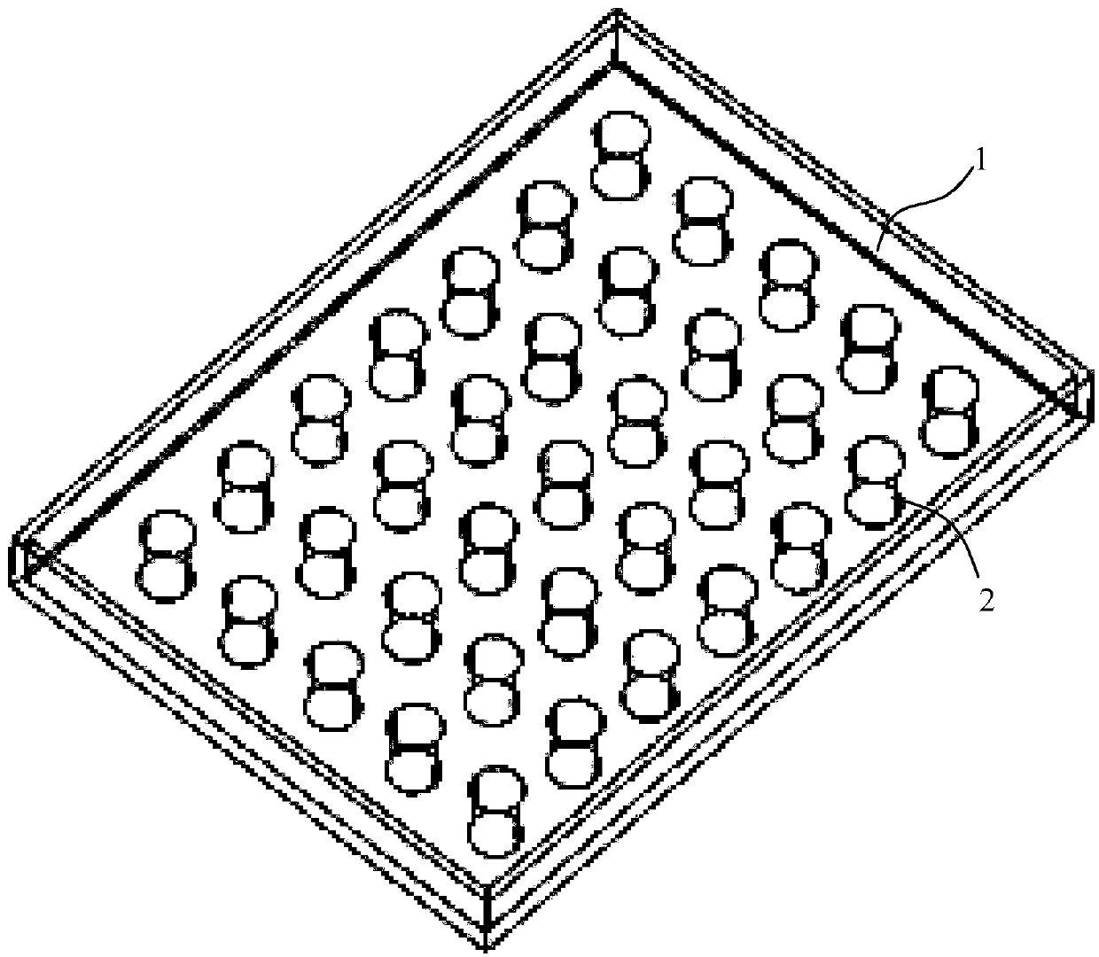
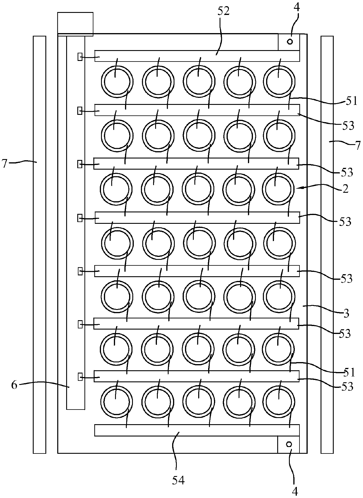

Image

  • Battery pack
  • Battery pack
  • Battery pack

Examples


Embodiment Construction

[0023] This part will describe the specific embodiment of the present invention in detail, and the preferred embodiment of the present invention is shown in the accompanying drawings. Each technical feature and overall technical solution of the invention, but it should not be understood as a limitation on the protection scope of the present invention.

[0024] In the present invention, if the direction (up, down, left, right, front and back) is described, it is figure 2 The structure shown is a reference description, but it is only for the convenience of describing the technical solution of the present invention, rather than indicating or implying that the technical features referred to must have a specific orientation, be constructed and operated in a specific orientation, so it cannot be understood as a reference to the technical solution of the present invention. Invention Limitations.

[0025] In the present invention, the meaning of "several" is one or more, and the mea...


PUM


Abstract

The invention discloses a battery pack applied to the field of battery modules. The battery pack comprises a tank body, an electric core array and a bracket, wherein a battery cell mounting structureis arranged on the tank body; the electric core array comprises a plurality of single electric cores, and the single electric cores are mounted on the battery cell mounting structure in a manner thatthe anodes face upwards; and the bracket is matched with the top of each single electric core, a conductor connecting component and an output electrode are arranged on the bracket, and the single electric cores of the electric cell array are linked by the conductor connecting component and are connected to an output electrode. By arranging the battery cell mounting structure on the tank body, thesingle electric cores are directly mounted on the battery cell mounting structure, so that the structure and the production process are simplified, and the manufacturing cost is lowered; and meanwhile, the single electric cores are mounted on the battery cell mounting structure in a manner that the anodes face upwards, and the single electric cores can be linked only through arranging the conductor connecting component on the bracket, so that the production process is further simplified.

Description

technical field [0001] The invention is used in the field of battery modules, and in particular relates to a battery pack. Background technique [0002] After the lithium-ion battery is assembled in groups, it has a very large capacity and energy density. At the same time, lithium-ion batteries are non-polluting and are a new type of green energy. They have been widely used in industries such as automobiles, mobile phones, and notebook computers. However, the efficiency issues in the lithium-ion grouping process, as well as issues such as raw materials and manufacturing costs are still under extensive and in-depth research. Especially during the assembly process of the module, it is difficult for the bracket to cover the battery cell, and flipping the module from the front to the back will also affect the efficiency. Therefore, there is a large room for innovation in this battery group structure. [0003] In the existing structure, the battery module has two upper and low...

Claims


Application Information

Patent Timeline
IPC IPC(8): H01M2/02H01M2/06H01M10/613H01M50/247H01M50/249H01M50/258H01M50/264H01M50/298
CPCH01M10/613H01M50/10H01M50/172Y02E60/10
Inventor 陆巍巍唐启滔许超前胡汉军刘安龙
Owner GUANGZHOU XIAOPENG MOTORS TECH CO LTD
Learn More