
System and method for testing multi-frequency point material

A material testing and testing method technology, applied in the direction of analyzing materials, conducting material analysis by electromagnetic means, measuring devices, etc., can solve the problems of less test frequency points, difficult test, small fixture size, etc., to eliminate the interference of miscellaneous mode, Reduce the difficulty of production and enhance the effect of magnetic field strength

Active Publication Date: 2019-03-26
CHINA ELECTRONIS TECH INSTR CO LTD
View PDF8 Cites 6 Cited by
  • Summary
  • Abstract
  • Description
  • Claims
  • Application Information

AI Technical Summary

Problems solved by technology

However, these two methods have some problems. For example, the transmission line method has low test accuracy, it is inconvenient to make samples, and the calibration accuracy is high; the resonant cavity method is based on the perturbation method. The principle of the resonant cavity method is to The material sample is placed in a closed or open resonant cavity, and the complex permittivity and complex permeability of the sample are determined according to the change of its resonant frequency and quality factor Q value before and after being placed, usually by placing the sample in the resonant cavity under an electric field The complex permittivity of the sample is measured at the minimum magnetic field and the maximum. The advantage of using the resonant cavity method to measure the dielectric properties of the material is that the test accuracy is high.
The disadvantage of measuring the dielectric properties of materials is that only point frequency tests can be performed, and due to the influence of mixed modes, there are few test frequency points available, and the measurable bandwidth is narrow, making it difficult to test high frequencies.
Moreover, the resonant cavity of the perturbation method is a cylindrical or rectangular hollow cavity structure, and the measurement must satisfy that the size of the sample to be measured is less than a few tenths of the cavity size, making the fixture size too small to be practical
The multi-frequency point test needs to be carried out in multiple resonant cavities working at different frequencies, which will greatly increase the test cost for metal resonant cavities, whether rectangular or circular. Electrical constant, unable to achieve multi-frequency point measurement

Method used


Image

  • System and method for testing multi-frequency point material
  • System and method for testing multi-frequency point material
  • System and method for testing multi-frequency point material

Examples


Embodiment Construction

[0050] The present disclosure will be further described below in conjunction with the accompanying drawings and embodiments.

[0051] It should be pointed out that the following detailed description is exemplary and is intended to provide further explanation to the present application. Unless defined otherwise, all technical and scientific terms used herein have the same meaning as commonly understood by one of ordinary skill in the art to which this application belongs.

[0052] It should be noted that the terminology used here is only for describing specific implementations, and is not intended to limit the exemplary implementations according to the present application. As used herein, unless the context clearly dictates otherwise, the singular is intended to include the plural, and it should also be understood that when the terms "comprising" and / or "comprising" are used in this specification, they mean There are features, steps, operations, means, components and / or combin...


PUM


Abstract

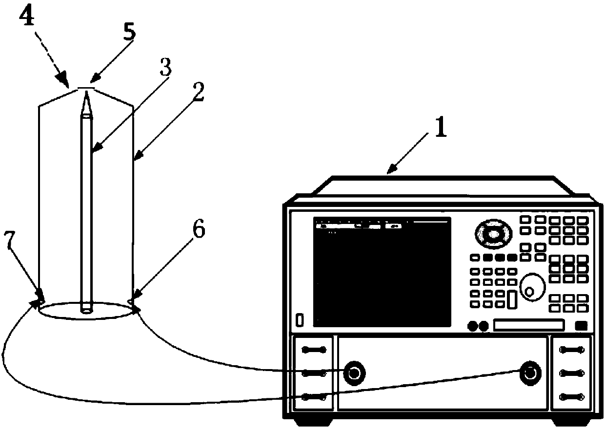
The invention discloses a system and method for testing a multi-frequency point material. By virtue of the advantage that a main mode of a coaxial opening type resonant cavity is not interfered by a parasitic mode, a dielectric constant of a tested material is calculated through the deviation of a resonant frequency point, and the rough position of the deviated resonant frequency point in a relatively high frequency band, so that the range of the testing frequency is extended. The method disclosed by the invention is suitable for measuring most materials and is particularly suitable for measuring the materials such as quartz, polytetrafluoroethylene, sapphires, corundum and ceramic with dielectric properties barely changed along the frequency.

Description

technical field [0001] The present disclosure relates to the technical field related to microwave measurement, and in particular, relates to a multi-frequency point material testing system and method. Background technique [0002] The statements in this section merely provide background information related to the present disclosure and do not necessarily constitute prior art. [0003] As an electromagnetic wave transmission medium, microwave materials have been widely used in various microwave fields, such as microwave circuits, communications, and radar stealth. The electromagnetic parameters of microwave materials completely determine the propagation characteristics of electromagnetic waves in it. Accurate understanding of electromagnetic parameter values ​​is essential for the application of microwave energy and various applications of materials in the microwave frequency range. The electromagnetic parameters of dielectric materials generally refer to the complex permit...

Claims


Application Information

Patent Timeline
IPC IPC(8): G01N27/60G01R27/26G01R23/16
CPCG01N27/60G01R23/16G01R27/2623G01R27/2658G01R27/2688
Inventor 江子奇胡大海赵锐殷志军王亚海
Owner CHINA ELECTRONIS TECH INSTR CO LTD
Learn More