Driving device with safety device
A technology for safety devices and driving devices, applied in fluid pressure actuating devices, fluid pressure actuating system safety, fluid pressure actuating system components, etc. Restrictions and other issues to achieve the effect of eliminating the phenomenon of speeding
- Summary
- Abstract
- Description
- Claims
- Application Information
AI Technical Summary
Problems solved by technology
Method used
Image

Examples
Embodiment 1
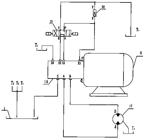
[0017] Such as figure 1 As shown, a driving device with a safety device includes a motor 4, a self-circulating pump 14, and a hydraulic system. The motor 4 is connected to the self-circulating pump 14, and a safety device 32 is connected to the control oil circuit of the hydraulic system. The safety device 32 It can be a safety valve or a relief valve. The connection relationship of the hydraulic system is as follows: the oil inlet S of the self-circulation pump 14 is connected to the oil outlet pipe of the oil tank 1, and the self-circulation pump 14 has a built-in charge pump oil outlet X3 and a reversing valve The P port of 19 is connected, the P port of the safety device 32 is connected with the P port of the reversing valve 19, and the T port of the other end of the safety device 32 is respectively connected with the T port of the reversing valve 19 and the oil return branch pipe T3 of the fuel tank 1 The ports A and B of the reversing valve 19 are respectively connected ...
Embodiment 2
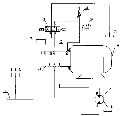
[0019] Such as figure 2 As shown, a driving device with a safety device whose speed is regulated by an overflow valve, in order to make the operating speed of the driving device steplessly adjustable, an overflow valve 35 is added to the basic structural schematic diagram of the driving device with a safety device A relief valve 35 is connected to the P port of the reversing valve 19, and the connection relationship of the hydraulic system is: the P port of the relief valve 35 is connected to the P port of the reversing valve 19, and the relief valve 35 The T oil port of the oil tank 1 is connected with the oil return branch pipe T3 of the oil tank 1.
Embodiment 3
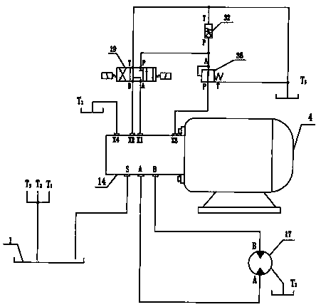
[0021] Such as image 3 As shown, a driving device with a safety device that uses a pressure reducing valve to adjust the speed, in order to make the operating speed of the driving device steplessly adjustable, a pressure reducing valve 36 is added to the basic structural schematic diagram of the driving device with a safety device , a pressure reducing valve 36 is connected in series between the oil outlet X3 of the built-in charge pump of the self-circulating pump 14 and the P port of the reversing valve 19, and the connection relationship of the hydraulic system is: the P port of the pressure reducing valve 36 and the automatic Circulation pump 14 is connected with oil outlet X3 of built-in charge pump, oil port A of pressure reducing valve 36 is connected with port P of reversing valve 19, oil port T of pressure reducing valve 36 is connected with oil return branch pipe of oil tank 1 T3 connection.
[0022] working principle:
[0023] The operating speed of the control s...
PUM
 Abstract
Description
Claims
Application Information
 - Generate Ideas
- Intellectual Property
- Life Sciences
- Materials
- Tech Scout
- Unparalleled Data Quality
- Higher Quality Content
- 60% Fewer Hallucinations
Browse by: Latest US Patents, China's latest patents, Technical Efficacy Thesaurus, Application Domain, Technology Topic, Popular Technical Reports.
© 2025 PatSnap. All rights reserved.Legal|Privacy policy|Modern Slavery Act Transparency Statement|Sitemap|About US| Contact US: help@patsnap.com