Eureka AIR delivers breakthrough ideas for toughest innovation challenges, trusted by R&D personnel around the world.

Pressurization and compression system

A technology of compression system and compressor, which is applied in the direction of liquid variable capacity machinery, pump control, variable capacity pump components, etc. It can solve the problems of high wear, high energy consumption, unfavorable use, etc., and achieve low wear and low energy consumption Effect

Inactive Publication Date: 2019-03-26
刘长江
View PDF0 Cites 0 Cited by
  • Summary
  • Abstract
  • Description
  • Claims
  • Application Information

AI Technical Summary

Problems solved by technology

Most air compressors are of reciprocating piston type, rotating blades or rotating screws; among them, the lubrication methods of screw compressors include water lubrication and oil lubrication, and oil-lubricated compressors use oil for lubrication. Atomize the lubricating fluid, in this case, the atomized lubricating fluid will enter the air line with the gas; however, the gas with oil is not conducive to use, so oil and gas separation treatment is required
[0003] The air compressor mainly consists of an air compressor, a liquid-gas separator and a filter device. Usually, when the air compressor is working, the air compressor sucks and compresses the gas, and the compressed gas will be mixed with the atomized lubricating liquid in the compressor. , so after the gas is compressed, it will be sent to the liquid-gas separation device for liquid-gas separation. At present, the common equipment has a load on the compressor when it is turned on, resulting in high energy consumption and high wear and tear.

Method used


Image

  • Pressurization and compression system

Examples


Embodiment Construction

[0017] The technical solution of the present invention will be further described below in conjunction with the accompanying drawings and through specific implementation methods.

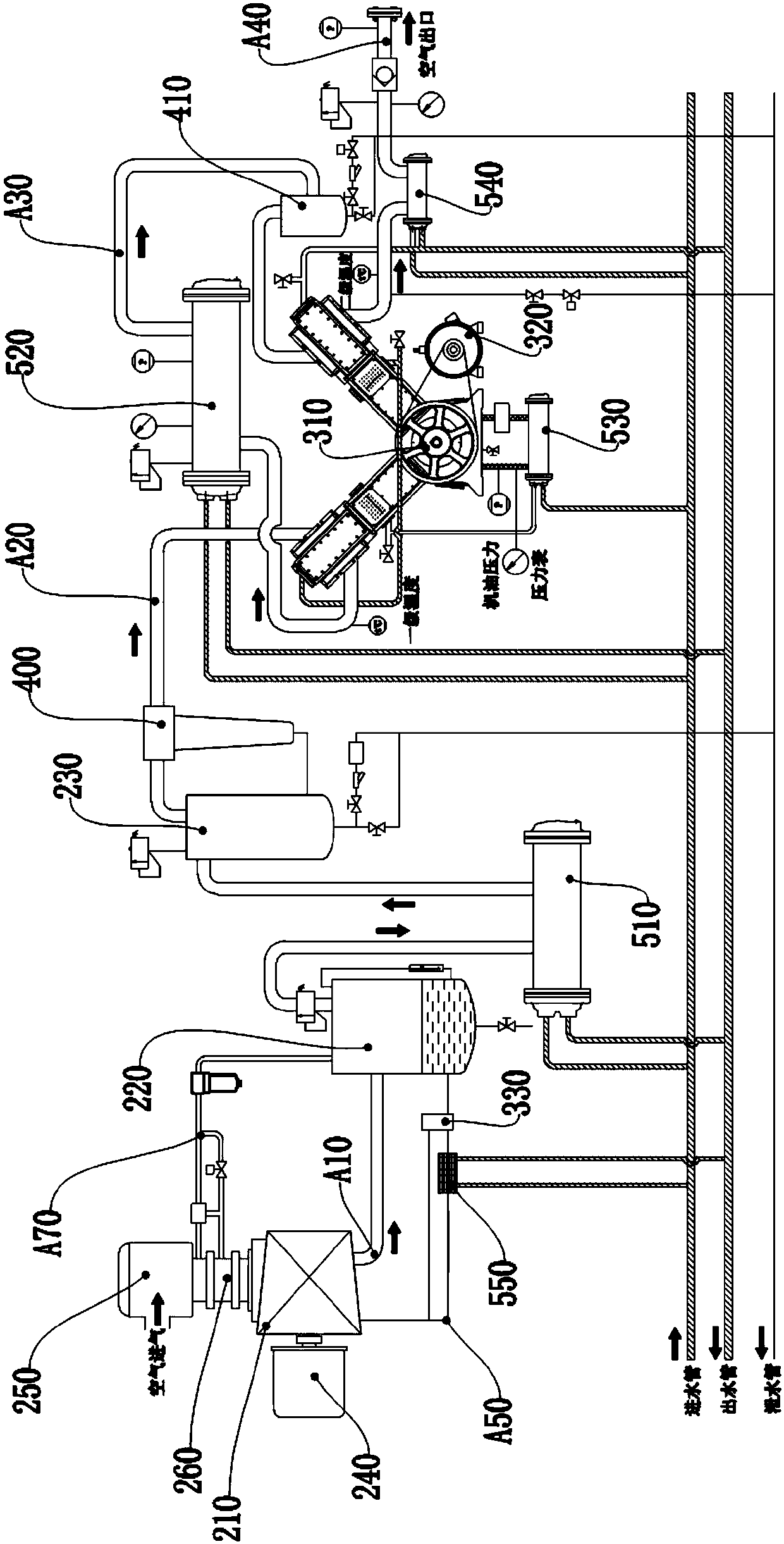
[0018] Such as figure 1 As shown, a pressurization and compression system includes an underframe, an air compression device and a booster device; the air compression device and the booster device are installed on the underframe; the bottom of the underframe is installed with a water inlet pipe main Road, outlet pipe main line and drain pipe main line; the air compression device includes an air intake line A10, and the air intake line A10 is sequentially equipped with a compressor 210, a separation tank 220 and an air storage tank 230, and the compressor 210 , the separation tank 220 and the air storage tank 230 are installed on the underframe, the air compression device also includes a first drive motor 240, and the first drive motor 240 is installed on the underframe, and the first drive motor 240 ...


PUM


Abstract

The invention discloses a pressurization and compression system. The pressurization and compression system comprises a base frame, an air compression device and a pressurization device; the air compression device and the pressurization device are installed on the base frame; a water inlet pipe main pipeline, a water outlet pipe main pipeline and a water drain pipe main pipeline are installed at the bottom of the base frame; the air compression device comprises an air inlet pipeline, wherein the air inlet pipeline is sequentially provided with a compressor, a separation tank and an air storagetank; the compressor, the separation tank and the air storage tank are installed on the base frame; an oil return pipeline is arranged between the compressor and the separation tank; and the air compression device further comprises a deflation pipeline. The booster compressor provided by the pressurization and compression system is provided with the deflation pipeline and an air inlet valve, and the deflation pipeline is used for controlling the air inlet valve so as to enable a low-load starting environment to be formed in the air inlet pipeline, so that the compressor is started in a low-load or zero-load environment, and therefore, compared with starting with load, the energy consumption is lower and the abrasion is less.

Description

technical field [0001] The invention relates to the field of air compressors, in particular to a booster compression system. Background technique [0002] An air compressor is a device used to compress gas. Air compressors are similar in construction to water pumps. Most air compressors are of reciprocating piston type, rotating blades or rotating screws; among them, the lubrication methods of screw compressors include water lubrication and oil lubrication, and oil-lubricated compressors use oil for lubrication. Atomize the lubricating fluid, in this case, the atomized lubricating fluid will enter the air line with the gas; however, the gas with oil is not conducive to use, so oil and gas separation treatment is required. [0003] The air compressor mainly consists of an air compressor, a liquid-gas separator and a filter device. Usually, when the air compressor is working, the air compressor sucks and compresses the gas, and the compressed gas will be mixed with the atomi...

Claims


Application Information

Patent Timeline
IPC IPC(8): F04B41/06F04B35/04F04B39/00F04B39/02F04B39/06F04B39/10F04B49/035
CPCF04B41/06F04B35/04F04B39/00F04B39/02F04B39/06F04B39/10F04B49/035
Inventor 刘长江
Owner 刘长江
Why Eureka
Eureka Blog
Learn More