
Self-rotary valve-type magnetic resistance head and its making method

A spin valve, magnetic head technology, applied in the manufacture of magnetic flux sensitive magnetic heads, magnetic recording heads, magnetic heads using thin films, etc., can solve problems such as distorted output voltage waveforms

Inactive Publication Date: 2002-11-27
FUJITSU LTD
View PDF7 Cites 0 Cited by
  • Summary
  • Abstract
  • Description
  • Claims
  • Application Information

AI Technical Summary

Problems solved by technology

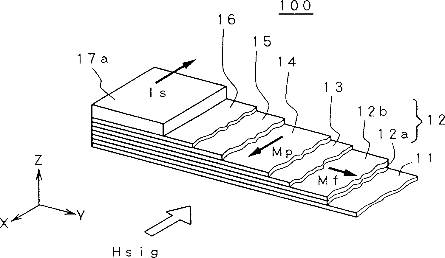
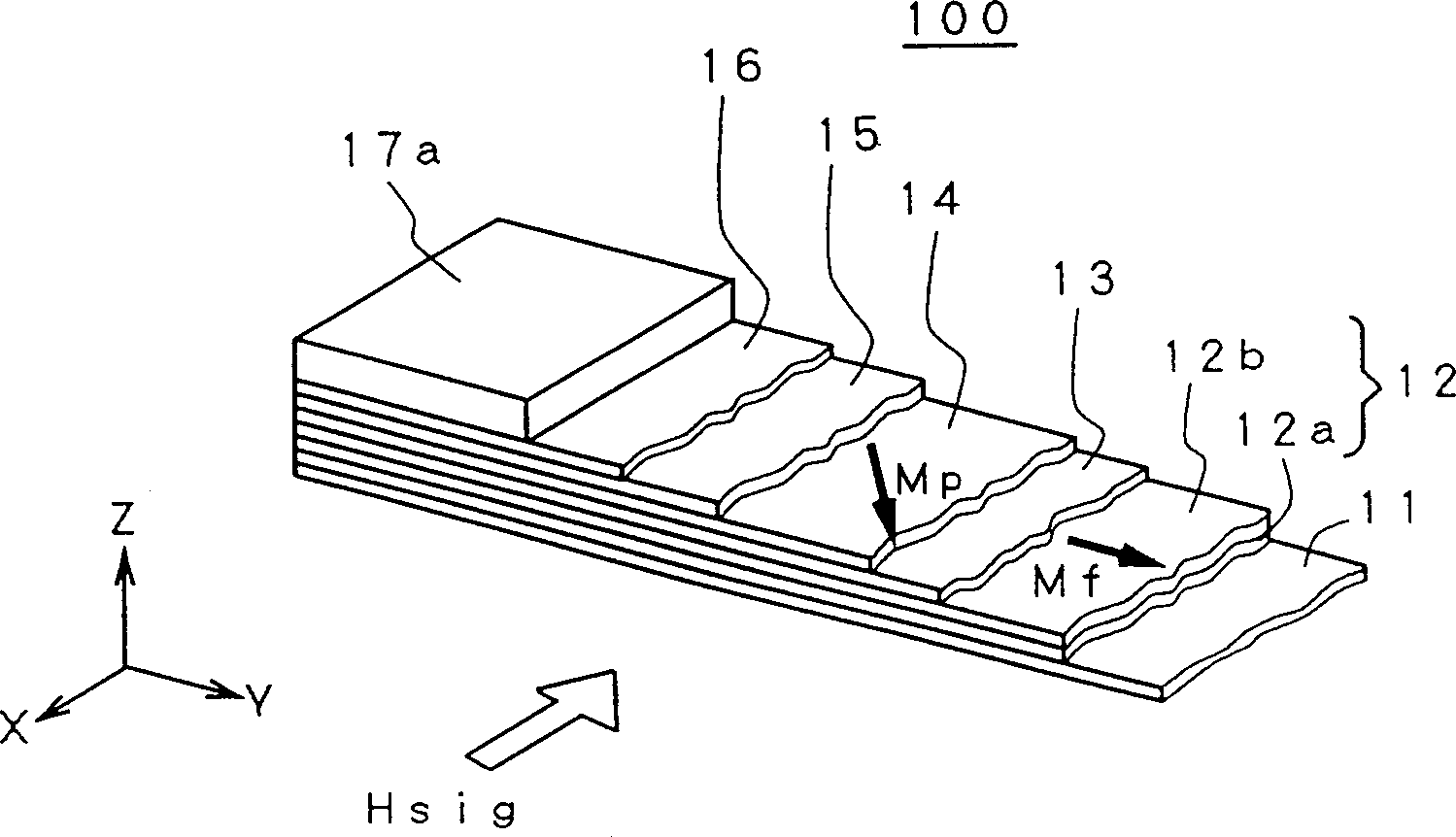
However, if the magnetization direction in the fixed magnetization layer 14 changes direction from the X-axis toward the Y-axis from the beginning, the spin-valve GMR head cannot produce a linear response characteristic to the externally applied magnetic field Hsig, and produces a distorted output voltage waveform

Method used


Image

  • Self-rotary valve-type magnetic resistance head and its making method
  • Self-rotary valve-type magnetic resistance head and its making method
  • Self-rotary valve-type magnetic resistance head and its making method

Examples


no. 1 example

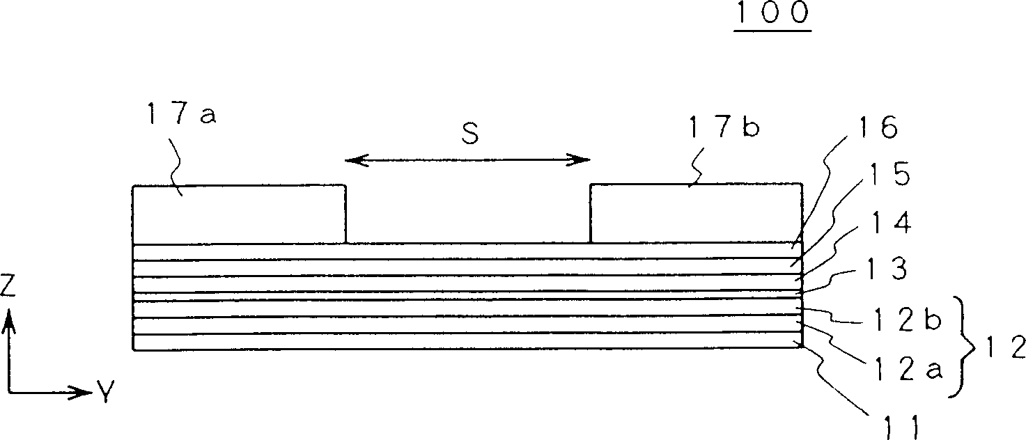
[0094] According to the first manufacturing method of the spin valve type GMR head according to the present invention, following the formation of the spin valve type GMR film, it is preferable to perform two-stage heat treatment after the above-mentioned heat curing process of the organic insulating layer 24. In the first stage, heat treatment is carried out by heating the spin-valve GMR film, for example, at 230°C under the action of a magnetic field of about 2500 Oersted along the Y axis (called in-field heat treatment), using an appropriate magnetic source, This enhances the magnetic anisotropy of the free magnetization layer 2 along the Y-axis direction. In the second stage, the second in-field heat treatment is performed on the spin-valve GMR film. The heat treatment is to heat the spin-valve GMR film to a certain level under the action of a magnetic field of about 2500 Oersted along the X-axis direction, for example. temperature, whereby the magnetization direction Mp in...

no. 2 example

[0100] According to the second manufacturing method of the spin valve type GMR head according to the present invention, the heat treatment of the third stage is performed after the spin valve type GMR film is formed in the following manner. In the first stage, the designated spin-valve GMR film is subjected to in-field heat treatment in order to fix the magnetization direction in the fixed magnetization layer 4 in the direction of the X-axis. This in-field heat treatment involves heating the spin-valve GMR film, for example at 280° C., in a magnetic field of 2500 Oersteds oriented in the X-axis direction using a suitable magnetic field source. In the second stage, another in-field heat treatment is specified for the spin-valve GRM film to enhance the magnetic anisotropy of the free magnetization layer 2 along the Y-axis direction. During this heat treatment, the spin-valve GMR film is heated, eg, at 230° C., in a magnetic field of about 2500 Oe oriented in the Y-axis direction...


PUM

PropertyMeasurementUnit
thicknessaaaaaaaaaa

Abstract

A method of fabricating a spin-valve GMR head with a fixed magnetization layer that maintains the magnetization in a desired direction. According to one aspect of the present invention, the method includes the steps of: forming a magnetic film comprising at least a free magnetization layer, a nonmagnetic metal layer, a fixed magnetization layer and a magnetic domain control layer; performing a first heat treatment in a magnetic field, Enhanced magnetic anisotropy of the free magnetization layer; maximum in magnetic field and higher than in previous processes. The second heat treatment is performed at a temperature to fix the magnetization direction in the fixed magnetization layer.

Description

technical field [0001] The present invention relates to a method for manufacturing a spin valve type magneto-resistive magnetic head, as well as such a magnetic head and a composite magnetic head manufactured by this method. Background technique [0002] In 1996, the data recording density of hard disk (HDD) had exceeded 1G / square inch. Such high-density recording has been achieved by developing a magnetoresistive (MR) type magnetic head having a higher read output power than a conventional thin film type magnetic head. The data recording density of HDDs has been increasing at an astonishing rate of 60% per year. In order to maintain this growth rate, further development of magnetic heads with excellent sensitivity is inevitable. [0003] From these circumstances, as a promising candidate for a magnetic head, various giant magnetoresistive thin films (hereinafter referred to as GMR films) have attracted attention because they can provide a large readout signal. Among vari...

Claims


Application Information

Patent Timeline
Patent Type & Authority Patents(China)
IPC IPC(8): G11B5/31G11B5/39
CPCB82Y10/00B82Y25/00G11B5/3163G11B5/3903G11B5/3967G11B2005/3996H01F10/3268G11B2220/2516
Inventor 金井均青岛贤一山田健一郎冈田光正清水栄二兼淳一
Owner FUJITSU LTD
Learn More