A knurled cutter head mounting assembly, straight cutter, and rotary cutter

A technology for installing components and knurling knives, which is applied in the field of knurling knives, can solve the problems of affecting the knurling effect of the knurling wheel, the swing of the knurling wheel, and the increase in the gap between the knurling wheel and the installation shaft, so as to improve convenience and avoid Oscillation, the effect of improving coaxiality

Inactive Publication Date: 2020-04-21
杨建成
View PDF10 Cites 0 Cited by
  • Summary
  • Abstract
  • Description
  • Claims
  • Application Information

AI Technical Summary

Problems solved by technology

[0004] However, during the use of the above-mentioned knurling tool, the installation shaft and the installation hole form an insertion fit, and the knurling wheel and the installation shaft form an insertion fit. For the knurling tool, the precision of the assembly process is very important. Among them, After the knurling wheel is processed for a period of time, due to the pressure on the knurling wheel, the gap between the knurling wheel and the installation shaft will increase, which will easily cause the knurling wheel to swing on the installation shaft and affect the knurling effect of the knurling wheel

Method used


Image

  • A knurled cutter head mounting assembly, straight cutter, and rotary cutter
  • A knurled cutter head mounting assembly, straight cutter, and rotary cutter
  • A knurled cutter head mounting assembly, straight cutter, and rotary cutter

Examples


Embodiment 1

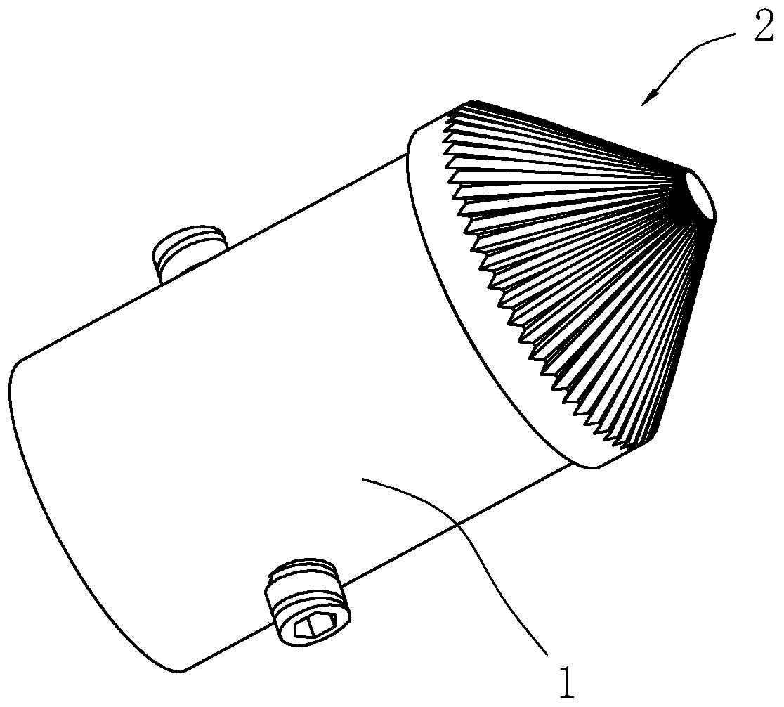
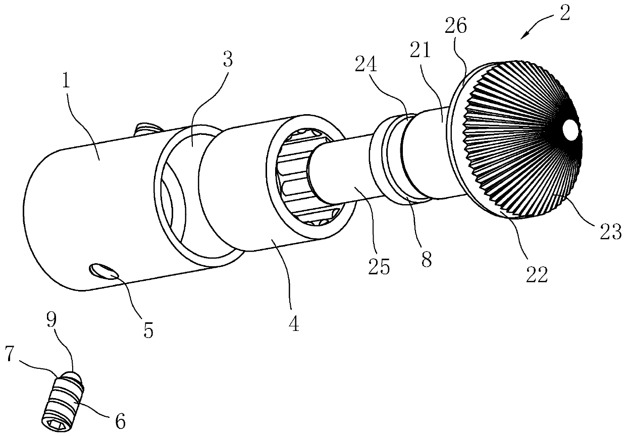
[0052] combine figure 1 and figure 2 As shown, a knurling cutter head mounting assembly includes a mounting head 1 and a knurling cutter head 2. A mounting hole 3 is opened on the mounting head 1, a needle bearing 4 is embedded in the mounting hole 3, and a needle bearing 4 is embedded in the mounting hole 3. There is a bearing hole, the bearing hole communicates with the mounting hole 3, the needle bearing 4 is embedded in the mounting hole 3 to be fixed, otherwise, the needle bearing 4 can be taken out from the mounting hole 3 by applying force to the needle bearing 4.

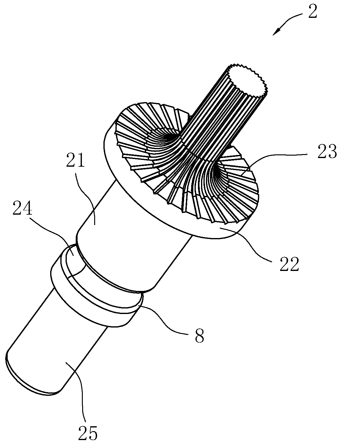
[0053] The knurled cutter head 2 includes a mounting column 21 and a knurled head 22 integrally formed on the mounting column 21. A knurled portion 23 is formed on the knurled head 22. The mounting column 21 is inserted into the bearing hole of the needle roller bearing 4. The column 21 is rotatable in the needle bearing 4 . Among them, the mounting column 21 is provided with an annular fastening groove 2...

Embodiment 2

[0062] combine Figure 7 and Figure 8 As shown, a straight tool includes a first handle 10 on which a knurled cutter head installation assembly is installed, and the knurled cutter head installation assembly is as described in the above technical solution.

[0063] The installation head 1 in the knurling cutter head installation assembly is integrally formed on the first handle 10, specifically, the installation head 1 is arranged in a cylindrical shape, and one end of the installation head 1 is integrally formed on the end of the first handle 10, and the installation hole 3 Opened at the other end of the installation head 1, the installation hole 3 and the installation head 1 are coaxially arranged. Thus, when the knurled cutter head 2 is installed in the installation hole 3 , the first handle 10 , the installation head 1 , the installation hole 3 and the knurled cutter head 2 are coaxially arranged.

[0064] It is worth noting that the first knife handle 10 is arranged in...

Embodiment 3

[0066] combine Figure 9 and Figure 10 As shown, a rotary tool includes a second handle 13, and the knurled cutter head installation assembly is rotatably installed in the rotation hole 15, and the knurled cutter head installation assembly is as described in the above technical solution.

[0067] The second handle of a knife 13 is arranged as a cuboid as a whole, and the end of the second handle of a knife 13 is provided with a turning groove 14, and the second handle of a knife 13 is provided with a turning hole 15 in the turning groove 14, and the turning hole 15 runs through the second handle of a knife 13, The knurled cutter head mounting assembly is fixed with a rotating shaft 16 on its mounting head 1, and the rotating shaft 16 is inserted into the rotating shaft 16 in the rotating hole 15, thereby realizing that the mounting head 1 is rotatably installed on the second handle 13 superior.

[0068] Wherein, the end of rotating shaft 16 is provided with mounting hole 3,...


PUM


Abstract

The invention discloses a knurling tool bit mounting assembly as well as a straight barrel tool and a rotary tool. The knurling tool bit mounting assembly comprises a mounting head and a knurling toolbit, wherein a mounting hole is formed in the mounting head; a rolling needle bearing is embedded into the mounting hole; the knurling tool bit comprises a mounting column and a knurling head which is integrally formed on the mounting column; a knurling part is processed on the knurling head; the mounting column is spliced into the rolling needle bearing; a ring-shaped fastening slot is formed inthe peripheral direction of the mounting column; fastening holes are formed in the two sides of the mounting head; and fastening parts, end parts of which are embedded into the ring-shaped fasteningslot, are in threaded connection in the fastening holes. The knurling head and the mounting column can be rotatably mounted in the rolling needle bearing as an integer, coaxiality between the mountingcolumn and the mounting hole can be improved by regulating the fastening parts, and rotation coaxiality of the knurling head is improved, so that contact stability between the knurling part and a workpiece can be improved while the knurling part is embossed on the workpiece to perform knurling operation, and therefore, a condition that the knurling head swings is avoided, and the knurling effecton the workpiece is improved.

Description

technical field [0001] The invention relates to the technical field of knurled cutters, in particular to a knurled cutter head mounting assembly, a straight cutter and a rotary cutter. Background technique [0002] Knurling is a process of embossing patterns on the surface of a workpiece with a knurling tool. [0003] The traditional knurling tool includes a handle, a mounting shaft and a knurling wheel. The end of the handle is provided with a mounting hole, and the mounting shaft is inserted into the mounting hole. Firmware, so as to realize the fixing of the installation shaft in the installation hole, wherein the knurled wheel is sleeved on the installation shaft, and the end of the installation shaft is provided with an anti-off screw for preventing the knurled wheel from falling off. Through the above knurling tool, the workpiece can be knurled by installing the knurling tool on the numerical control lathe. [0004] However, during the use of the above-mentioned knur...

Claims


Application Information

Patent Timeline
Patent Type & Authority Patents(China)
IPC IPC(8): B23P9/02
CPCB23P9/02
Inventor 杨建成
Owner 杨建成
Why Eureka
Try Eureka