Eureka AIR delivers breakthrough ideas for toughest innovation challenges, trusted by R&D personnel around the world.

Electrical equipment safety protection device

A technology for safety protection devices and power equipment, which is applied in the direction of measuring devices, electrical equipment shells/cabinets/drawers, measuring electricity, etc., and can solve the problem of not installing lifting devices, not installing clamping devices, and inconvenient detection of the inner shell of electric equipment boxes and other issues, to achieve the effect of whether the leakage is convenient

Inactive Publication Date: 2019-03-22
GUANGXI UNIV
View PDF17 Cites 3 Cited by
  • Summary
  • Abstract
  • Description
  • Claims
  • Application Information

AI Technical Summary

Problems solved by technology

[0004] The invention provides a safety protection device for electric equipment, which has the advantages of being convenient for the user to repair and replace the electric equipment on the bottom plate and for the user to detect whether the electric equipment is leaking electricity, and solves the problem that the existing electric equipment protection device is not installed well. It is not convenient for users to repair and replace the internal electrical equipment; and the existing electrical equipment protection device does not have a suitable leakage detection device, which makes it inconvenient for users to detect whether the electrical equipment is leaking and whether the inner shell of the electrical box is live; and the existing power equipment protection device does not have a good clamping device installed inside, and then it is not convenient to fix and replace the parts attached to the power equipment inside the housing

Method used


Image

  • Electrical equipment safety protection device
  • Electrical equipment safety protection device
  • Electrical equipment safety protection device

Examples


Embodiment Construction

[0024] The following will clearly and completely describe the technical solutions in the embodiments of the present invention with reference to the accompanying drawings in the embodiments of the present invention. Obviously, the described embodiments are only some, not all, embodiments of the present invention. Based on the embodiments of the present invention, all other embodiments obtained by persons of ordinary skill in the art without making creative efforts belong to the protection scope of the present invention.

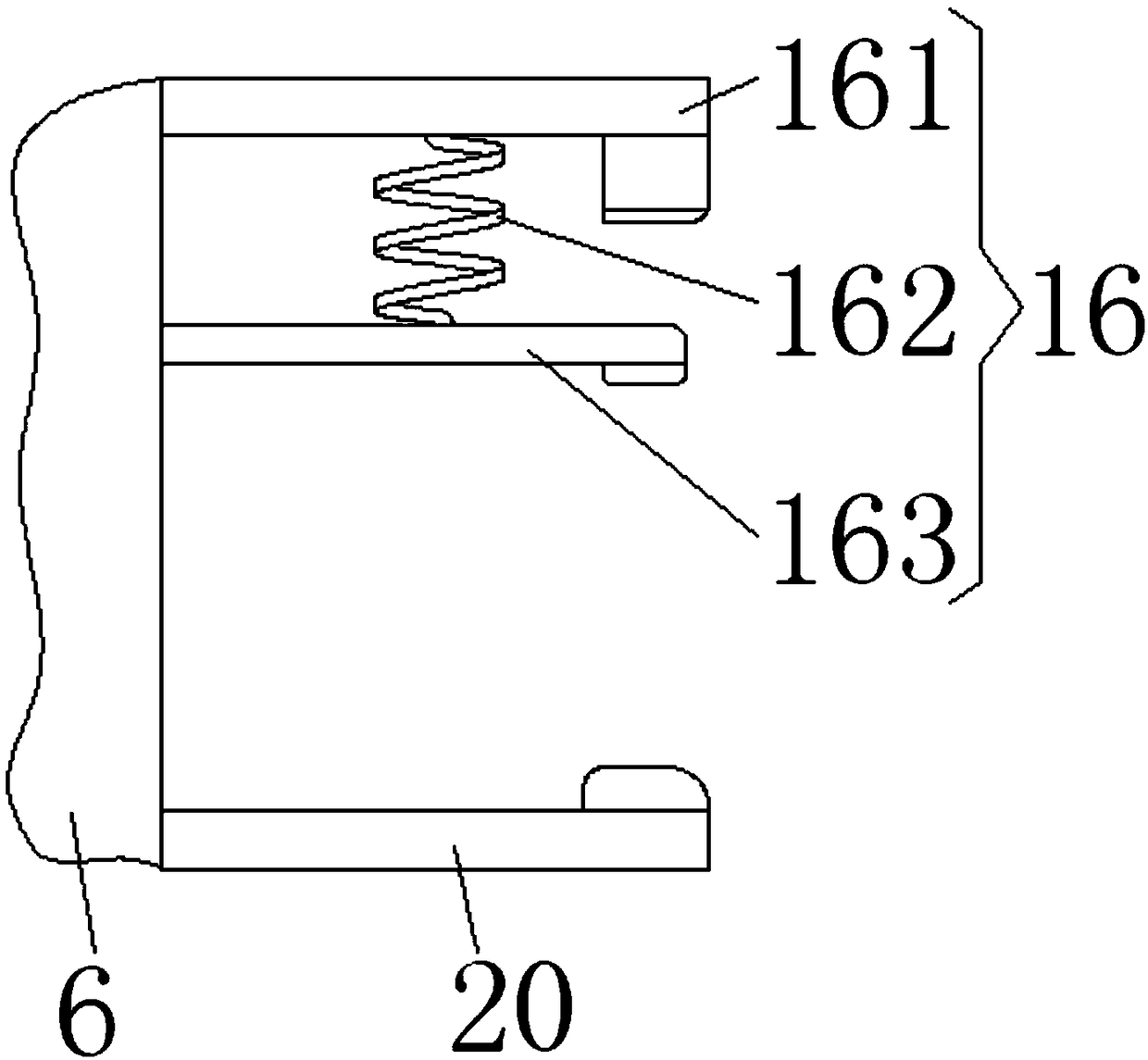
[0025] see Figure 1-4 , a safety protection device for electric equipment, comprising a base plate 1 and a clamping device 4 fixedly installed on the bottom of the base plate 1, the middle part of the upper surface of the base plate 1 is fixedly connected with a fixed plate 6, and boxes are fixedly installed on the left and right sides of the upper surface of the base plate 1 Body 7, the two boxes 7 are symmetrical to each other with the vertical center line ...


PUM


Abstract

The invention relates to the technical field of safety protection devices and provides an electrical equipment safety protection device which comprises a bottom plate and a clamping device fixedly installed at the bottom of the bottom plate; a fixing plate is fixedly connected to the middle of the upper surface of the bottom plate; box bodies are fixedly installed on the left side and the right side of the upper surface of the bottom plate, and the two box bodies are symmetrical with the center line in the vertical direction of a protection shell as the symmetry axis. Through the cooperation of driving motors, driving gears, connecting sleeves, threaded rods, driven gears and support frames, when the left driving motor is started clockwise, the protection shell can be separated from the bottom plate; at the moment, the electrical equipment on the bottom plate is not covered, a user can conveniently overhaul and replace the electrical equipment on the bottom plate, and the problems thatit is inconvenient for the user to overhaul a conventional electrical equipment safety protection device and it is troublesome to replace some parts thereof are solved.

Description

technical field [0001] The invention relates to the technical field of safety protection devices, in particular to a safety protection device for electric equipment. Background technique [0002] Power equipment mainly includes power generation equipment and power supply equipment. Power generation equipment is mainly power plant boilers, steam turbines, gas turbines, water turbines, generators, transformers, etc. Power supply equipment is mainly transmission lines of various voltage levels, transformers, contactors, etc. In real life, in order to increase the use speed of power equipment, a protective device is often added to the outside of the power equipment. [0003] The existing electric equipment protection device does not have a good lifting device, which makes it difficult for users to repair and replace the internal electric equipment; and the existing electric equipment protection device does not have a suitable leakage detection device, which makes it difficult fo...

Claims


Application Information

Patent Timeline
IPC IPC(8): H05K5/02G01R19/145G01R31/02
CPCG01R19/145G01R31/50H05K5/0217H05K5/0234
Inventor 蔡义明
Owner GUANGXI UNIV
Why Eureka
Eureka Blog
Learn More