
Fast neutron imaging system

An imaging system and neutron technology, applied in the measurement of neutron radiation, instruments, radiation measurement, etc., can solve the problems such as the large size of the translation stage, the difficulty in meeting the requirements of different fields of view and resolution, and the large load. The effect of simple space setting, improving neutron detection efficiency and light collection efficiency

Active Publication Date: 2019-03-22
HEFEI INSTITUTES OF PHYSICAL SCIENCE - CHINESE ACAD OF SCI
View PDF7 Cites 9 Cited by
  • Summary
  • Abstract
  • Description
  • Claims
  • Application Information

AI Technical Summary

Problems solved by technology

[0005] Existing neutron photography devices mostly use a structure with a fixed distance between the conversion screen and the CCD camera, which is difficult to meet the requirements of different field of view and resolution
Before the present invention, China published a patent application "High-Speed ​​Neutron Camera Device" on November 16, 2011. The application number is ZL201110179473.9. It can respond to different field of view and resolution requirements, but in this design, the lens and CMOS camera are placed in a lead shielding box, and the lead shielding box is placed on the X translation stage, and the X translation stage drives the lens and CMOS camera While moving, it needs to drive the lead shielding box to move synchronously, the translation stage is bulky and has a heavy load

Method used


Image

  • Fast neutron imaging system
  • Fast neutron imaging system
  • Fast neutron imaging system

Examples


Embodiment 1

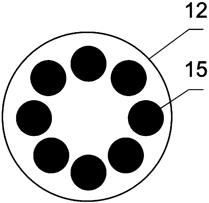
[0040] Such as Figure 1-5 As shown, a fast neutron imaging system in this embodiment includes a neutron conversion screen 1 , a mirror 2 , an image detector 3 , an optical adjustment frame 4 , an obscura 5 , a shielding module 6 and a computer control system 7 . Wherein, the dark box 5 is specifically an "L"-shaped box with a boss extending outward from one side, the extension direction of the boss is facing the neutron beam, and the side wall of the dark box 5 at the side end of the boss is provided with a shielding module 6, and the dark box 5 It contains a neutron conversion screen 1 , a mirror 2 , an image detector 3 and an optical adjustment frame 4 .

[0041] The neutron conversion screen 1 is specifically arranged inside the black box 5 facing the incident direction of the neutron beam. The other side of the neutron conversion screen 1 is provided with a mirror 2 at an angle of 45 degrees to the incident direction of the neutron beam. Equipped with image detector 3 . ...

Embodiment 2

[0051] A fast neutron imaging system of this embodiment has basically the same structure as that of Embodiment 1, the main differences are: (1) the neutron conversion screen 1 is circular, with a diameter of 150 mm and a thickness of 32 mm; the neutron-proton conversion layer 11 has a thickness of 2mm, the electron multiplication layer 13 has a thickness of 5mm, and the fluorescent layer 14 has a thickness of 25mm; (2) The channel aperture of the microchannel plate is 20 μm, the channel inclination angle is 8°, and the channel spacing is 50 μm. A voltage of 2 kV is applied at both ends of the microchannel plate.

Embodiment 3

[0053] A fast neutron imaging system of this embodiment has basically the same structure as that of Embodiment 1, the main differences are: (1) the neutron conversion screen 1 is circular, with a diameter of 150 mm and a thickness of 30 mm; the neutron-proton conversion layer 11 has a thickness of 2mm, the electron multiplication layer 13 has a thickness of 4mm, and the fluorescent layer 14 has a thickness of 15mm; (2) the channel aperture of the microchannel plate is 15 μm, and the channel inclination angle is 8 o , the channel spacing is 50 μm, and a voltage of 1kV is applied to both ends of the microchannel plate; (3) the image detector 3 adopts a silicon photomultiplier array; Composed of avalanche photodiodes (APD), it has the characteristics of high single-photon counting detection sensitivity, high gain, low bias voltage, insensitivity to magnetic fields, and compact structure. The neutrons transmitted by the sample react with the neutron conversion screen 1 to generate...


PUM


Abstract

The invention provides a fast neutron imaging system. The fast neutron imaging system comprises a neutron conversion screen, a mirror, an image detector, an optical adjustment frame, a camera obscura,a shielding module and a computer control system, wherein the neutron conversion screen, the mirror, the image detection and the optical adjustment frame are arranged in the camera obscura, and the shielding module is arranged at one side, facing a neutron beam, of the camera obscura; the neutron conversion screen comprises a neutron-proton conversion layer, a proton energy selection layer, an electron multiplication layer and a fluorescent layer; the image detector adopts a silicon photomultiplier tube array or an image enhancement CCD camera; the optical adjustment frame comprises a first translation stage and a second translation stage; one end of the first translation stage is provided with the mirror, the other end of the first translation stage is connected with a second translationstage, and the second translation stage is provided with the image detector opposite to the mirror; the computer control system remotely controls the movement of the first translation stage and second translation stage. The fast neutron imaging system has the advantages that the structure is simple and compact, and the imaging requirements of different views fields and resolutions can be met.

Description

technical field [0001] The invention relates to the technical field of neutron photography, in particular to a fast neutron imaging system. Background technique [0002] Neutron radiography is a radiographic non-destructive testing method that uses different neutron mass attenuation coefficients of different materials to obtain the internal structure of samples. The high energy of fast neutrons makes it more penetrating than thermal neutrons and cold neutrons, which provides conditions for the detection of internal information of some heavy objects. Fast neutron radiography technology makes up for the deficiencies of thermal neutron radiography technology and X-ray radiography technology in the on-site detection of thick samples or large pieces, and is an important supplement to thermal neutron radiography technology and X-ray radiography technology. Fast neutron photography has broad application space and development prospects, especially in aerospace, nuclear materials, a...

Claims


Application Information

Patent Timeline
Patent Type & Authority Applications(China)
IPC IPC(8): G01T3/02G01T3/06G01T3/00
CPCG01T3/00G01T3/02G01T3/06
Inventor 吴宜灿李雅男张早娣章勇胡丽琴王芳
Owner HEFEI INSTITUTES OF PHYSICAL SCIENCE - CHINESE ACAD OF SCI
Learn More