
Chemical fiber yarn oiling groove drum type winding machine

A winder and oil tank technology, which is used in the transportation of filamentous materials, thin material processing, transportation and packaging, etc. Good oiling effect, less yarn wear and less friction

Pending Publication Date: 2019-03-22
GUANGDONG ESQUEL TEXTILES CO LTD
View PDF0 Cites 7 Cited by
  • Summary
  • Abstract
  • Description
  • Claims
  • Application Information

AI Technical Summary

Problems solved by technology

The oiling device uses the sponge to absorb oil and rubs against the yarn to achieve oiling. This oiling method is unstable in oiling, and the surface of the sponge is rough. There is a large friction between the yarn and the sponge, which often leads to The yarn is torn and damaged. Therefore, the winding effect of the traditional grooved drum winding machine is poor, which directly causes serious quality problems in the cloth surface woven in the subsequent weaving process.

Method used

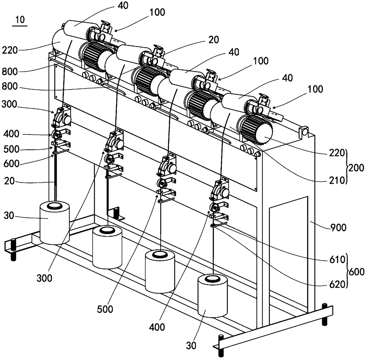
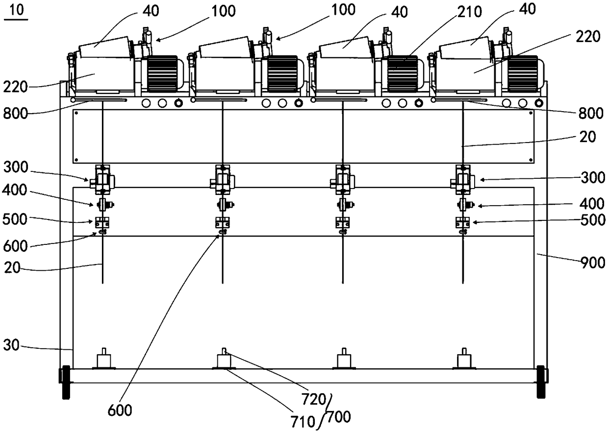
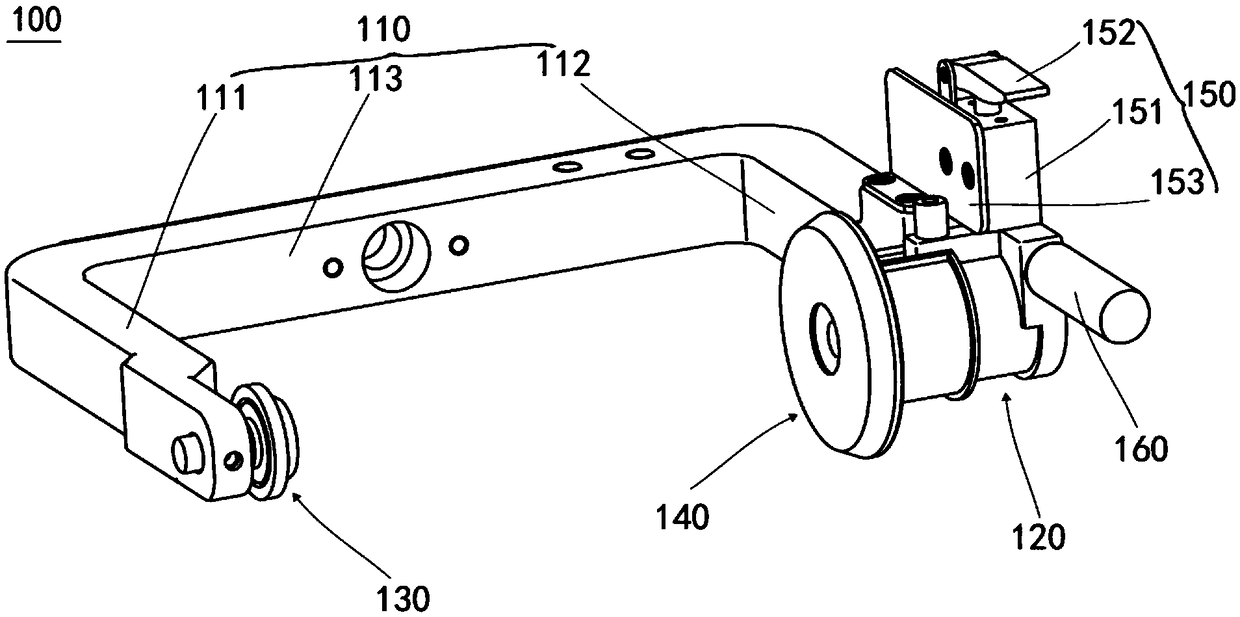

Image

  • Chemical fiber yarn oiling groove drum type winding machine
  • Chemical fiber yarn oiling groove drum type winding machine
  • Chemical fiber yarn oiling groove drum type winding machine

Examples


Embodiment Construction

[0041] In order to facilitate the understanding of the present invention, the present invention will be described more fully below with reference to the associated drawings. Preferred embodiments of the invention are shown in the accompanying drawings. However, the present invention can be embodied in many different forms and is not limited to the embodiments described herein. On the contrary, these embodiments are provided to make the understanding of the disclosure of the present invention more thorough and comprehensive.

[0042] It should be noted that when an element is referred to as being “fixed” to another element, it can be directly on the other element or there can also be an intervening element. When an element is referred to as being "connected to" another element, it can be directly connected to the other element or intervening elements may also be present. When an element is said to be "located on" another element, it can be directly connected to the other elem...


PUM


Abstract

The invention discloses a chemical fiber yarn oiling groove drum type winding machine. The chemical fiber yarn oiling groove drum type winding machine comprises a machine frame, an oiling device, a swing frame device and a winding device, wherein the oiling device comprises an oil passing box used for containing oil materials, an oil passing wheel arranged in the oil passing box and an oil wheel driving part connected with the oil passing wheel, the oil passing box is provided with an oil passing window, the oil passing wheel part protrudes out of the oil passing window, and the oil wheel driving part is used for driving the oil passing wheel to rotate; the swing frame device is arranged on the machine frame and is used for allowing a conical bobbin to be installed; the winding device comprises a groove drum and a winding driving part, the groove drum is rotatably connected with the machine frame, the groove drum is close to the swing frame device, and is used for being in contact withand rotationally matched with the conical bobbin on the swing frame device, the winding driving part is connected with the groove drum and used for driving the groove drum to rotate, and the rotationof the groove drum drives the conical bobbin to rotate so as to realize winding of yarns passing through the oiling device and being oiled. The chemical fiber yarn oiling groove drum type winding machine is good in winding effect.

Description

technical field [0001] The invention relates to the field of textile equipment, in particular to an oiling tank drum type winding machine for chemical fiber yarn. Background technique [0002] In the textile industry, the winding process is to process the dyed package yarn into a tapered package yarn that is easy to unwind. The stability of the winding equipment directly affects the quality of the cloth surface in the weaving process. The traditional tank-type winding machine with oiling device includes a frame, a cradle device and an oiling device. An oiling device is installed in front of each spindle position of the winding machine, and an oiling device is installed in the oil storage tank of the oiling device. sponge. The oiling device uses the sponge to absorb oil and rubs against the yarn to achieve oiling. This oiling method is unstable, and the surface of the sponge is rough, and there is a large friction between the yarn and the sponge, which often leads to The ya...

Claims


Application Information

Patent Timeline
IPC IPC(8): B65H71/00B65H54/46B65H54/54
CPCB65H54/46B65H54/54B65H71/00
Inventor 吴惠忠张伟一廖良叶伟
Owner GUANGDONG ESQUEL TEXTILES CO LTD
Learn More