
Transport device for machined parts of numerical control machine tool

A technology of CNC machine tools and transportation devices, applied in tool storage devices, manufacturing tools, workshop equipment, etc., can solve problems such as damage to processing parts, scratches, poor shock absorption effect, etc., to achieve convenient use, reduce the number of damage, Impact and damage reduction effects

Inactive Publication Date: 2019-03-22
张培良
View PDF0 Cites 2 Cited by
  • Summary
  • Abstract
  • Description
  • Claims
  • Application Information

AI Technical Summary

Problems solved by technology

[0003] The object of the present invention is to provide a transport device for CNC machine tool processing parts, which can protect the processing parts by shock absorbers during transportation, reduce the impact and damage to the processing parts due to bad road conditions, and reduce the processing parts. The number of damages and the advantages of being convenient for people to use solve the problem that people need to transport the processed parts to other places after processing with CNC machine tools. Most of the transportation devices currently used do not have shock absorption effect or have poor shock absorption effect. This may cause damage to the processed parts that have just been processed, deform or scratch the processed parts, and affect people's use.

Method used


Image

  • Transport device for machined parts of numerical control machine tool
  • Transport device for machined parts of numerical control machine tool
  • Transport device for machined parts of numerical control machine tool

Examples


Embodiment Construction

[0016] The following will clearly and completely describe the technical solutions in the embodiments of the present invention with reference to the accompanying drawings in the embodiments of the present invention. Obviously, the described embodiments are only some of the embodiments of the present invention, not all of them. Based on the embodiments of the present invention, all other embodiments obtained by persons of ordinary skill in the art without making creative efforts belong to the protection scope of the present invention.

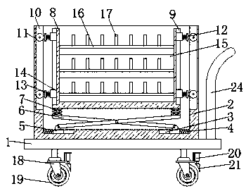
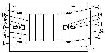
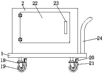
[0017] see Figure 1-3 , a transport device for CNC machine tool processing parts, comprising a base plate 1, a push rod 24 is fixedly connected to the right side of the top of the base plate 1, the surface of the push rod 24 is provided with anti-skid lines, and both sides of the bottom of the base plate 1 are fixedly connected to wheel seats 18. The right side of the bottom of the wheel seat 18 is fixedly connected with an electric push rod 20,...


PUM


Abstract

The invention discloses a transport device for machined parts of a numerical control machine tool. The transport device includes a bottom plate, wherein the top of the bottom plate is fixedly connected with a box body; first sliding troughs are formed on both sides of the bottom of the inner cavity of the box body; one sides of the inner cavities of first sliding troughs are fixedly connected withfirst springs; sliders are fixedly connected with the opposite sides of the first springs; the tops of the sliders are connected with moving rods through rotating shafts; and the sides, away from thesliders, of the tops of the moving rods are fixedly connected with second springs. Through the fitting of the bottom plate, the box body, the first sliding troughs, the first springs, the sliders, the moving rods, the second springs, a U-shaped frame, long troughs, second sliding troughs, pulleys, connecting members, third springs, placement plates, cushions and partition plates, the impact and damage on the machined parts caused by poor road conditions are reduced, the number of the damaged machined parts is reduced, and the transport device is convenient for people to use.

Description

technical field [0001] The invention relates to the technical field of transportation tools, in particular to a transportation device for parts processed by a numerical control machine tool. Background technique [0002] CNC lathe processing is a high-precision, high-efficiency automatic machine tool that uses digital information to control the displacement of parts and tools. It is a solution to the problems of aerospace product parts such as changeable varieties, small batches, complex shapes, and high precision. An effective way to realize high-efficiency and automatic processing. After processing with CNC machine tools, people need to transport the processed parts to other places. Most of the transportation devices currently used do not have shock-absorbing effects or have poor shock-absorbing effects. It may cause damage to the processed parts that have just been processed, deform or scratch the processed parts, and affect people's use. Contents of the invention [0...

Claims


Application Information

Patent Timeline
Patent Type & Authority Applications(China)
IPC IPC(8): B25H3/02B25H3/04B25H5/00
CPCB25H3/02B25H3/04B25H5/00
Inventor 张培良
Owner 张培良
Learn More