Concrete recycling device

A technology of concrete and sedimentation tanks, which is applied in the direction of grain processing, etc., can solve problems such as improper waste gas treatment, daunting enterprises, difficulties in implementing reuse, etc., and achieves the effect of low cost and convenient use

Inactive Publication Date: 2019-03-22
成都尊华荣域科技有限公司
View PDF0 Cites 7 Cited by
  • Summary
  • Abstract
  • Description
  • Claims
  • Application Information

AI Technical Summary

Problems solved by technology

[0013] At present, although my country is gradually promulgating relevant laws and regulations, the national standard-level regulations for the reuse of construction waste are not comprehensive enough, and only some special economic zones have relatively detailed guidelines for the reuse of construction waste, which have not been well popularized in other regions
If there is no clear specification to guide, it will be more difficult to implement the project of recycling. Even if it is implemented, it is likely to cause some problems: such as incomplete treatment of the factory, so that the waste gas in the processing process is not properly treated and processed The quality of the final finished product is lower than the expected value. For this risk, more companies will be discouraged

Method used


Image

  • Concrete recycling device
  • Concrete recycling device
  • Concrete recycling device

Examples


Embodiment 1

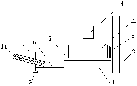
[0033] Such as Figure 1-Figure 4 As shown, in this embodiment, a concrete recycling device includes a base 1 for placing waste materials, a support 2 arranged on the base 1, a rolling board 3 located above the base 1, and a roller plate 3 arranged on the support 2 and driven The driving mechanism for the rolling plate 3 to move in the vertical direction; the base 1 is connected to the deposition tank 7; the deposition tank 7 is connected to the screw lifting mechanism 11.

[0034]Place construction solid waste such as abandoned concrete structures and discarded boards on the base 1, use the driving mechanism to drive the rolling plate 3 to move towards the base 1, and use the rolling plate 3 to exert pressure on the construction solid waste to break the construction solid waste , Structures such as wood boards and plastic boards are crushed under pressure and separated from their internal metal structures such as screws, and concrete structures are crushed under pressure and ...

Embodiment 2

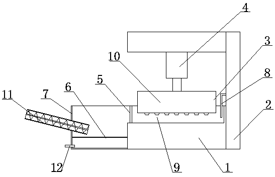
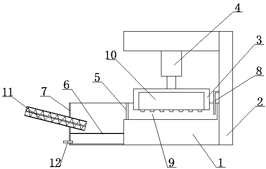
[0039] On the basis of the above embodiments, in this embodiment, the base 1 is provided with an isolation plate 5; the isolation plate 5 is provided with an opening communicating with the deposition pool 7; There is a water inlet pipe 8, and the water inlet pipe 8 is located on the side opposite to the opening. The isolation plate 5 can prevent the solid waste from splashing due to force during the pressurization process, thereby avoiding safety accidents, and can play a role in drainage, controlling the water flow to move toward the sedimentation tank to avoid liquid leakage. The water inlet pipe 8 is used to guide the water flow to the base 1, so that the solution is more convenient to use, helps to reduce labor intensity, and facilitates the realization of automatic control. The water inlet pipe 8 is provided with a pressure regulating valve to control the flow of water, so as to facilitate the control of the largest particle size of the solid debris that can be taken away...

Embodiment 3

[0041] On the basis of the above embodiments, in this embodiment, a filter layer 6 located below the screw lifting mechanism 11 is arranged in the deposition tank 7 . The filter layer 6 can intercept the concrete fragments and only let the water flow through, so that the mud and the liquid are stratified, so as to avoid excessive moisture in the mud taken away by the screw lifting mechanism 11 . In this embodiment, other parts not described are the same as those in the foregoing embodiments, so details are not repeated here.


PUM


Abstract

The invention discloses a concrete recycling device. The concrete recycling device comprises a base used for containing waste, a support arranged on the base, a grinding plate located above the base and a drive mechanism arranged on the support and used for driving the grinding plate to move in the vertical direction. The base is connected with a settling pond, and the settling pond communicates with a spiral lifting mechanism. The concrete recycling device has the beneficial effects that concrete, building plates and other solid waste can be treated, the concrete, the plates and other structures are crushed and separated from metal materials, and therefore metal, the concrete, wood, plastic and other materials are classified and recycled respectively, and concrete recycling can be achieved; and the concrete recycling device has the advantages of being convenient to use and low in use cost and can effectively separate various different kinds of waste.

Description

technical field [0001] The invention relates to the field of construction waste treatment, in particular to a concrete recycling device. Background technique [0002] According to the source, construction waste can be divided into five categories: land excavation, road excavation, demolition of old buildings, building construction and building material production waste. From the perspective of the formation of construction waste, it mainly includes: concrete, mortar, tiles, metal, wood, brick, plastic, and some sundries and organic matter. [0003] my country's existing construction area has reached 60 billion square meters, and the annual construction waste discharge is about 1.55 to 2.4 billion tons. Construction waste has become the second largest solid waste in cities. In the construction process, concrete is the most important building material, and the production of 1m3 concrete requires about 1700-2000kg of sand and gravel. It can be seen that in the production proc...

Claims


Application Information

Patent Timeline
IPC IPC(8): B02C1/14B02C23/14
CPCB02C1/14B02C23/14B02C2201/02
Inventor 梁欣
Owner 成都尊华荣域科技有限公司
Why Eureka
Try Eureka