Pyridine nitrogen enriched carbon nanotube catalyst as well as preparation method and application thereof
A carbon nanotube and pyridine nitrogen technology, applied in the field of electrocatalysis, can solve the problems of application limitation, low percentage of pyridine nitrogen, etc., and achieve the effects of good stability, high current density and good application prospect.
- Summary
- Abstract
- Description
- Claims
- Application Information
AI Technical Summary
Problems solved by technology
Method used
Image
Examples
Embodiment 1
[0041] The preparation method of pyridine nitrogen-enriched carbon nanotube catalyst comprises the following steps:
[0042] 600 mg of 1-10 phenanthroline and 200 mg of multi-walled carbon nanotubes were dispersed in a mixed solution of 25 ml of ethanol and 25 ml of deionized water, stirred at room temperature for 12 hours, then evaporated to dryness at 105 °C, and ground in an agate mortar Then, the electrocatalyst precursor was obtained; the electrocatalyst precursor was taken and placed in a porcelain boat, heat-treated in a tube furnace, heated from room temperature to 700°C at 5°C / min, held for 3 hours, and then cooled at 3.3°C / min At room temperature, the heat treatment atmosphere is an ammonia gas atmosphere to obtain the pyridine nitrogen-enriched carbon nanotube catalyst.
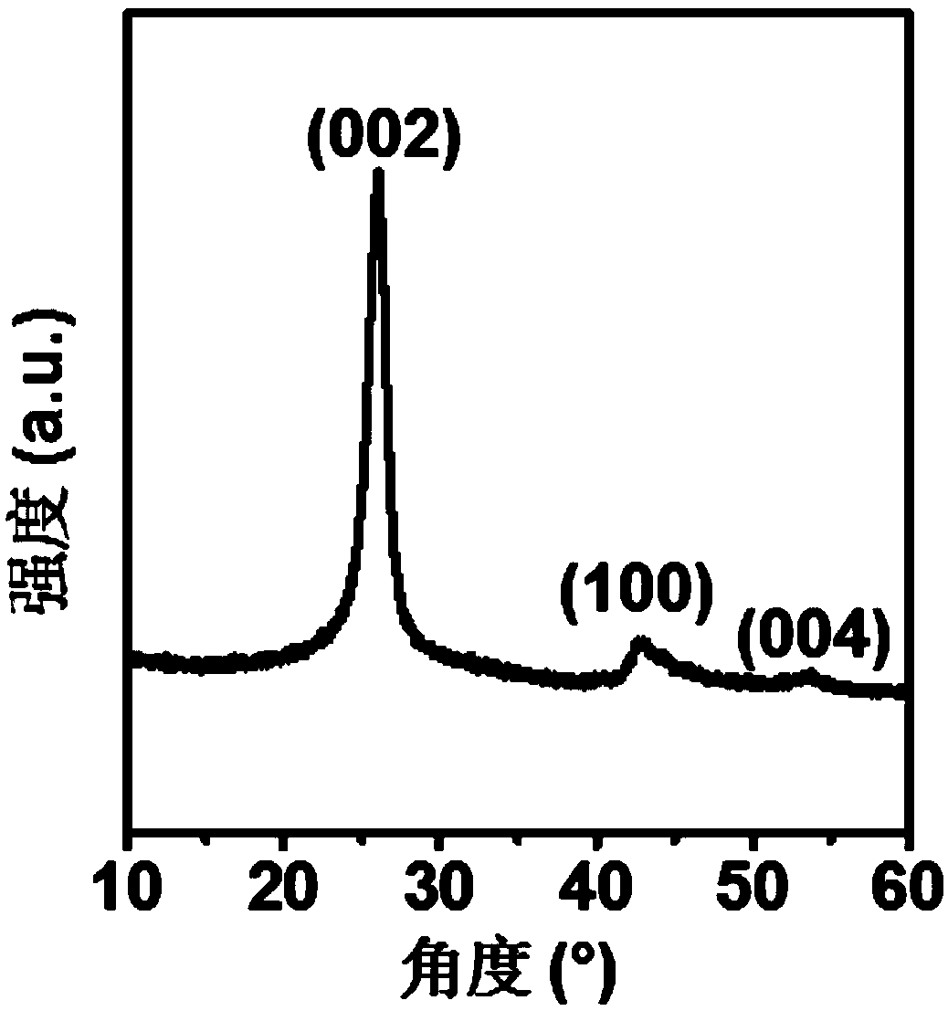
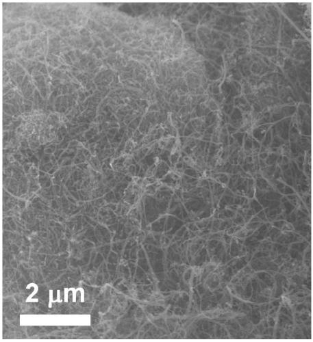
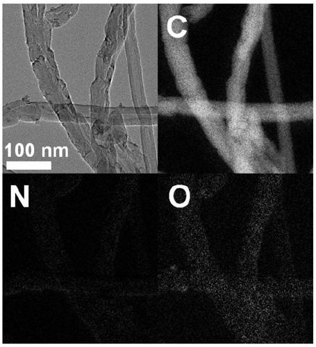
[0043] The X-ray diffraction curve of the catalyst prepared in this example is as follows figure 1 As can be seen from the figure, the catalyst prepared in this example has three typical crystal p...
Embodiment 2
[0054] Example 1 was repeated, except that the heat treatment temperature was changed from 700 °C to 500 °C, and the morphology of the obtained electrocatalyst was similar to that of the electrocatalyst obtained in Example 1, but the total nitrogen content was reduced to 2.0%, and the percentage of pyridine nitrogen was 58.7 %.
[0055] The catalyst prepared in this example was prepared in 0.5M NaHCO saturated with carbon dioxide 3 The Faradaic efficiency-voltage diagram of carbon monoxide obtained by electrolysis in aqueous solution is as follows Image 6 The resulting electrocatalyst product selectivity is shown to be similar to the electrocatalyst obtained in Example 1.
[0056] The catalyst prepared in this example was prepared in 0.5M NaHCO saturated with carbon dioxide 3 The carbon monoxide current density-voltage diagram obtained by electrolysis in aqueous solution is as follows Figure 7 shown. The maximum current density of carbon monoxide is 13 mA / cm 2 .
Embodiment 3
[0058] Example 1 was repeated, except that the heat treatment temperature was changed from 700 °C to 300 °C, and the morphology of the obtained electrocatalyst was similar to that of the electrocatalyst obtained in Example 1, but the total nitrogen content was reduced to 1.0%, and the percentage of pyridine nitrogen was 79.6%.
[0059] The catalyst prepared in this example was prepared in 0.5M NaHCO saturated with carbon dioxide 3 Carbon monoxide Faradaic efficiency-voltage obtained by electrolysis in aqueous solution as Image 6 shown. The product selectivity of the obtained electrocatalyst is not much different from that of the electrocatalyst obtained in Example 1.
[0060] The catalyst prepared in this example was prepared in 0.5M NaHCO saturated with carbon dioxide 3 The carbon monoxide current density-voltage diagram obtained by electrolysis in aqueous solution is as follows Figure 7 shown. The maximum current density of carbon monoxide is 8 mA / cm 2 .
PUM
 Abstract
Description
Claims
Application Information
 - R&D
- Intellectual Property
- Life Sciences
- Materials
- Tech Scout
- Unparalleled Data Quality
- Higher Quality Content
- 60% Fewer Hallucinations
Browse by: Latest US Patents, China's latest patents, Technical Efficacy Thesaurus, Application Domain, Technology Topic, Popular Technical Reports.
© 2025 PatSnap. All rights reserved.Legal|Privacy policy|Modern Slavery Act Transparency Statement|Sitemap|About US| Contact US: help@patsnap.com


