
Drainage monitoring system and method based on image recognition

A monitoring system and image recognition technology, which is applied in the field of medical devices, can solve the problems of long time, sometimes up to several days or even weeks, labor-intensive, delay of treatment, etc., to reduce medical risks, reduce work burden, and facilitate installation Effect

Active Publication Date: 2019-03-22
刘铁楠
View PDF4 Cites 8 Cited by
  • Summary
  • Abstract
  • Description
  • Claims
  • Application Information

AI Technical Summary

Problems solved by technology

Because the current medical drainage devices generally still rely on manual inspection for monitoring, automatic monitoring of the liquid in the drainage device cannot be realized, and patients generally need drainage treatment for a long time, sometimes up to several days or even weeks, so it will consume a lot of manpower , especially at night or when there is a shortage of personnel, it is not convenient to observe and monitor the drainage volume, color, turbidity, etc. of the drainage fluid
Moreover, it often happens that the patient's condition deteriorates, resulting in a sudden increase in the drainage fluid or a change in its properties, such as blood vessel rupture causing massive bleeding, or drainage fluid mixed with abnormal substances and changing from clear and thin to turbid, all of which require medical attention It is difficult for the conventional manual observation and monitoring mode to detect this change in time, and it is easy to delay the disease, causing serious consequences and even endangering the life of the patient.

Method used


Image

  • Drainage monitoring system and method based on image recognition
  • Drainage monitoring system and method based on image recognition
  • Drainage monitoring system and method based on image recognition

Examples


Embodiment Construction

[0030] The application will be further described in detail below in conjunction with the accompanying drawings and embodiments. It should be understood that the specific embodiments described here are only used to explain related inventions, rather than to limit the invention.

[0031] The monitoring system of the present invention is applicable to various medical procedures involving drainage. During the drainage process, body fluids such as peritoneal fluid and pleural fluid generally flow out from the chamber to be drained through the medical drainage catheter, and are finally contained in the drainage container. The drainage container can It is all drainage containers in the medical process, such as drainage bottles, drainage bags, negative pressure drainage devices or suction devices during surgery, etc., which are generally placed under the chamber to form a hydraulic pressure difference to achieve drainage of body fluids.

[0032] As described above, the existing draina...


PUM


Abstract

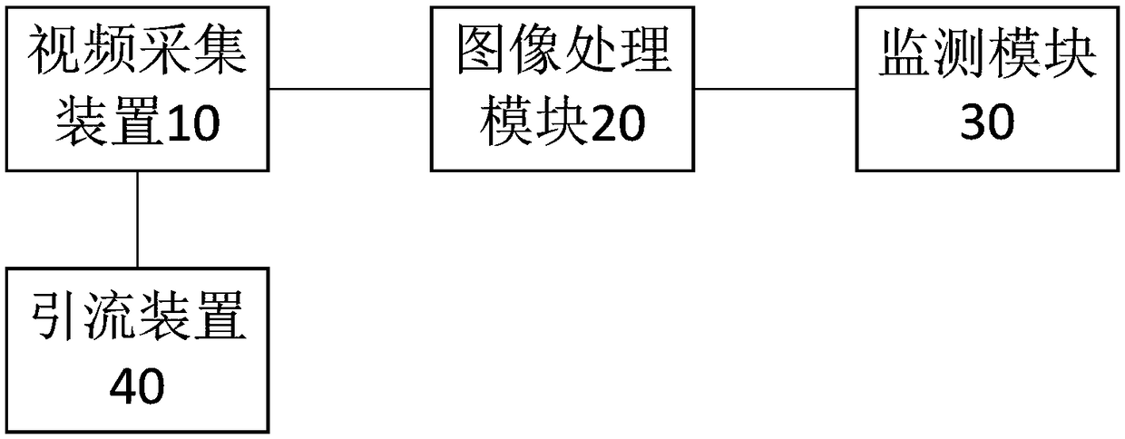
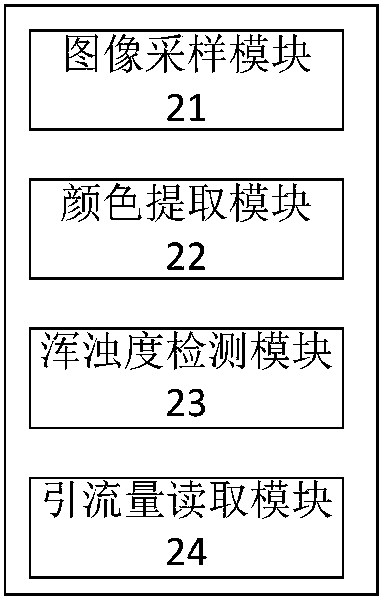
The invention relates to a drainage monitoring system and method based on image recognition. According to an exemplary embodiment, the drainage monitoring system comprises at least one video acquisition device, an image processing module, and a monitoring module, wherein the video acquisition device is used for acquiring video stream data of a drainage liquid; the image processing module is connected with the at least one video acquisition device, and is used for receiving the video stream data and processing the video stream data to obtain drainage data of the drainage liquid; and the monitoring module is connected with the image processing module, and is used for receiving and monitoring the drainage data; and meanwhile, a central monitoring module is arranged on the monitoring system, and is used for monitoring monitoring data of a plurality of the monitoring modules in real time. The monitoring device can centrally monitor multiple drainage data such as drainage volume, color, turbidity and the like of the drainage liquid, monitor relevant data and start alarm, so that the work burden of medical staff is effectively reduced, and the medical risks are reduced.

Description

technical field [0001] The present invention generally relates to the field of medical devices, and more specifically, relates to a drainage monitoring system and method based on image recognition. Background technique [0002] Body fluid drainage devices are one of the most common medical devices in the medical field, and are widely used in various clinical departments. The most commonly used drainage devices in existing medical applications are mainly drainage bottles or drainage bags. In the process of clinical diagnosis and treatment, the drainage device relies on gravity or negative pressure for drainage, and is mostly placed at the bottom of the hospital bed. [0003] During the drainage process, the indicators that characterize the changes of the disease include the drainage volume, color, and turbidity of the drainage fluid. The degree reflects the condition of the drainage site tissue. Because the current medical drainage devices generally still rely on manual ins...

Claims


Application Information

Patent Timeline
IPC IPC(8): A61M1/00G06K9/00
CPCA61M1/734G06V20/40
Inventor 刘铁楠吴春涛艾梦池
Owner 刘铁楠
Learn More